Introduction to the 1502DD linear lab power supply
What is the 1502DD?
This device is a linear power supply that delivers a DC voltage between 0 V and 15 V with a maximum current of 2 A. The power supply is equipped with an automatic electronic fuse that can be set to a trip current of 600 mA to 2 A. If the unit delivers more current than the set value, the output voltage goes to zero volts and a short buzzer sounds. After a few seconds, the output voltage will be restored. If the current supplied is still higher than the set value, the output voltage goes back to zero volts, etc.
The power supply is housed in a sturdy metal case measuring 12.5 cm by 15.0 cm by 19.5 cm. It weighs 1.9 kg and is mounted on four sturdy rubber feet.
On the back there is a fuse holder and the serial transistor type 2N3773. This is isolated from the housing by means of a fairly thick piece of foil. It is therefore clear that the large thermal power generated in the series transistor in a linear power supply must be dissipated via the metal of the case. If you set such a power supply to 5 V and draw the maximum current of 2 A, then about 30 W is still dissipated in the transistor. We are therefore very curious to discover whether saving on an (expensive) heatsink will not result in the case and the series transistor becoming far too hot.
 |
| The front and rear of the 1502DD lab power supply. (© 2022 Jos Verstraten) |
Manufacturer, suppliers and prices
The 1502DD appears to be a very popular product supplied by dozens of mail order companies at rather different prices and under different names. We found names like Yihua, Yaxun, Yaogong, Dazheng, Baku, Best and Element. On the back of the model delivered to us, the manufacturer is GuangZhou Yihua Electronic Equipment Co.
As the cheapest offer we found a price of € 24.42 (Element) at the time of writing this article. But that may be different now that you are reading this. We were surprised to find that a Dutch mail order company offers this power supply for € 106.59. Would anyone be fooled by this?
We ordered our copy via AliExpress at the 'Pro Repair Tool Store' for € 33.73.
The packaging of the power supply
The 1502DD is delivered in a sturdy cardboard box with protective styrofoam. Besides the power supply, this box contains two small cables and an English manual. Why these 65 cm long cables are equipped with measuring pins is a mystery to us.
 |
| The 1502DD is delivered well packed. (© AliExpress) |
The operation of the 1502DD
The picture below shows the front panel in detail. The two three-digit LED-displays have a height of 14 mm and are therefore easy to read. The leftmost knob is a rotary potentiometer that allows you to set the trip current. Please note that this power supply does not have a constant current mode! You only set a current value at which the electronic fuse 'blows' and the output voltage goes to zero. Setting this current is easy. In the idle state, the ammeter will of course display '0.00'. If you now turn the potentiometer, the meter will automatically indicate the trip current. This value remains on the screen for two seconds, after which the meter switches back to displaying the current supplied.
Next to this potentiometer is a rotary switch with which you can select five pre-programmed output voltages:
- 1.5 V
- 3.6 V
- 4.5 V
- 6.0 V
- 7.2 V
In the sixth position, you can adjust the output voltage yourself with the two right-hand potentiometers. The right one is for coarse adjustment, the left one for fine adjustment. Since the display has a resolution of only 100 mV, you can use these two potentiometers to set a voltage of exactly 12.0 V, for example.
What inspired the designers of this power supply to choose these fixed output voltages is a mystery to us. The standard voltage of 5.0 V should not have been missing, of course, and the use of a fixed voltage of 7.2 V is unclear to us.

There are two LEDs between the four buttons. The left one lights up when the electronic fuse becomes active. Quite unnecessary because of the built-in beeper that goes loud in such a case. The right one never lit up on our model, so its function is unclear.
On the left bottom side is the big on/off switch that is easy to operate. When switching on the power supply, the current display indicates the trip current value for two seconds, which is very handy. Next to this switch are three 4 mm banana sockets. The yellow one is marked 'GND'. That must mean that this socket is connected to the metal chassis and to the earth of the mains plug. The first is indeed the case, the second is not!
 |
The front panel of the 1502DD power supply. |
The first point of criticism
The mains cable is indeed only two-wire and ends in a flat two-pole mains plug. This means that the notation 'GND' at the yellow banana socket is nonsense and that there should never have been a 'CE' mark on the front panel. But it also means that this power supply does not comply with the most basic requirement of any mains powered electrical device in a metal housing: make sure this housing is earthed! If the 1502DD has a short circuit in the mains transformer, the housing of this device can be connected to the mains live without you noticing it. Until you accidentally touch the housing and receive a potentially life-threatening shock.
Our advice: if you decide to buy this power supply, immediately replace the two-wire mains lead with a three-wire one and fit an earthed mains plug to this lead. As you will see in the pictures of the interior of this device, there is a solder tab under one of the mounting screws of the transformer to which you can solder the earth wire of the power cord.
The manufacturer's specifications
According to the manufacturer, the 1502DD meets the following specifications:
- Line voltage: 220 Vac ~ 240 Vac, 50 Hz
- Output voltage: 0.0 Vdc ~ 15.0 Vdc
- Noise and ripple: Less than 0.5 mVRMS (5 Hz ~ 1 MHz) at 1 A
- Input stability: 0.01 % ±2 mV
- Output stability: 0.01 % ±2 mV
- Temperature coefficient: less than 300 ppm/°C
- Output current: 2.0 A max.
- Current limitation: 0.6 A ~ 2.0 A
- Resolution voltage measurement: 100 mV
- Resolution current measurement: 10 mA
- Ambient temperature: +40 °C max.
Not bad specs indeed! But whether they are true.... we shall see!
The electronics in the 1502DD
Opening the enclosure
The U-shaped cover of the housing is fixed with eight self-tapping bolts on the also U-shaped bottom and is quickly removed. The photo below shows the electronics hidden in the case.
A number of things immediately catch the eye:
- The transformer is extremely small for a device that is claimed to be able to deliver 2 A of current.
- This transformer, type YF-EI57*26A, has two secondary windings, one of 10 V and one of 20 V. The first is used to supply the digital circuits in the device. The second provides the voltage for the actual power supply.
- The wiring is rather sloppy. The 230 V wiring is not separated from the rest of the wiring and goes criss-cross through the empty space in the device.
- The mains switch is double-pole, but only half of it is used. Even when switched off, the mains live can therefore be present in the device. All the more reason to replace the mains cable with an earthed one!
 |
| The internal of the 1502DD power supply. (© 2022 Jos Verstraten) |
- Some solderings are, as it should be, finished with shrinking tube, others are not. The two wires that are soldered to the mains switch are not finished with shrink tubing, but the three wires that go to the series transistor are.
- The wires carrying the mains voltage are also soldered very sloppily on the mains switch, just look at the photo below.
- All wiring to the PCBs is done with PCB connectors.
- All screw connections and all PCB connectors are fixed with some kind of red lacquer.
- The wiring that can carry the maximum current of 2 A is a bit too thin to our taste, we would have preferred a bigger diameter.
- The bolts that secure the transformer to the chassis are simply attached to the lacquered metal on the outside of the housing, without toothed lock washer. However, these bolts must ensure that the chassis is connected to earth!
 |
| Wiring up the mains switch and the series transistor. (© 2022 Jos Verstraten) |
The two PCBs
The electronics are located on two PCBs. It looks as if the analogue part is entirely on one PCB and the digital part is entirely on the other. This construction is also worth criticising.
- The 20 V winding comes on the lower circuit board via the two yellow wires. In this corner, three components are close together: the bridge rectifier, the primary smoothing capacitor and the current sensor resistor. Next to this last component is another electrolytic. Both the bridge rectifier and the current sensor will probably become quite hot when the power supply is loaded with a large current. The two electrolytic capacitors therefore also become quite hot, which is not good for the life expectancy of these components. The PCB really could not have been designed in a more wrong way!
- The primary smoothing capacitor is 2,200 μF ~ 35 V. Apart from the fact that we would have preferred it in a cooler place, we would have chosen a 4,700 μF counterpart at this location in the schematic.
- The control system is built around an LM723CN, an ancient but good voltage stabiliser.
- The rotary switch on the front panel is converted to a slide switch on the PCB thanks to an ingenious construction.
- Behind this slide switch, there are five adjustment potentiometers on the PCB. These are used to adjust the five fixed output voltages.
- On the top PCB we can recognise a double op-amp of the type UTC358D.
- The inscription on the two large DIL-ICs has been made unreadable.
- Now it is clear why the 'LED' between the two potentiometers for the voltage setting is never lit. There is no LED at this location on the PCB!
 |
| The two circuit boards of the 1502DD power supply. (© 2022 Jos Verstraten) |
The schematic of the 1502DD
We found four schematics of this power supply on the internet, but they are all slightly different from each other and clearly cannot be the schematic of the device we tested. So undoubtedly, there are various versions of the 1502DD in circulation, as unfortunately so often happens with Chinese products.
The 1502DD linear power supply tested
The maximum output voltage
The example delivered to us delivers, unloaded and according to its own display, a maximum DC voltage of 15.1 V. According to our reference meter (Fluke 8842A), this voltage is equal to 15.664 V.
The accuracy of the internal voltage meter
The large difference between what our Fluke displayed and what the 1502DD's own display indicated gave us a bad feeling that the internal meter is not very accurate. In the table below, you can see this hunch confirmed by a number of voltage settings in a no-load condition. Our 1502DD always indicates a smaller voltage than is present on the output terminals.
 |
| The accuracy of the voltmeter. (© 2022 Jos Verstraten) |
Fixed voltage accuracy
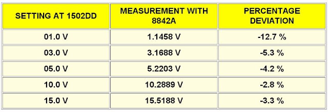
We switched on the five fixed output voltages, again with no load, and observed what the built-in meter said and what our Fluke found. The built-in meter showed a deviation of 100 mV to 200 mV in all modes. The deviations indicated by the Fluke, summarised in the table below, are smaller. Apparently, the five potentiometers are not adjusted at the factory with the internal meter as reference, but with an external meter.
 |
| The accuracy of the fixed output voltages. (© 2022 Jos Verstraten) |
The accuracy of the internal current meter
We set the power supply to an output voltage of 5.0 V and connected the 1502DD to a digital constant current sink. Our reference meter ET3255 was switched to DC current range in series with the output of the power supply. The results are again summarised in the table below.
 |
| The accuracy of the ammeter. (© 2022 Jos Verstraten) |
The output stability at 5.0 V
The output stability is the parameter that defines how stable the output voltage of a power supply remains when you increase the load current from zero to the maximum value. This measurement also measures the ripple and noise on the output at different load currents. The output voltage is measured with the Fluke 8842A, the noise/ripple with the Philips PM2454 millivoltmeter. This measures average values and has a bandwidth of 2 MHz. The results are summarised in the table below.
From this measurement, you can calculate the internal resistance of the power supply as 0.1388 V divided by 2.0 A equals 69.4 mΩ.
These results seem very good for such a cheap power supply. However, this becomes quite different when we are going to evaluate the behaviour of the power supply when a large current is drawn over a long period of time, read more later!
 |
| Output stability at 5.0 V output voltage. (© 2022 Jos Verstraten) |
The output stability at 12.0 V
The same measurements were performed at an output voltage of 12.0 V. At this voltage, the 1502DD fails if you draw more current than 1.5 A. The electronic fuse, although set for 2.0 A, then blows continuously. The average value of ripple and noise also increases sharply at 1.5 A.
 |
| Output stability at 12.0 V output voltage. (© 2022 Jos Verstraten) |
The ripple and noise on the oscilloscope
The Philips millivoltmeter measures the average values of the noise and ripple. More interesting is what the oscilloscope has to tell about the same disturbances on the output voltage.
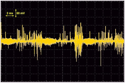
In the oscillogram below, you can see the result with a no-load output voltage of 12.0 V. There is hardly any 50 Hz or 100 Hz ripple to be seen, which is logical without load, but there is all the more noise to be seen. Moreover, there are quite a few small spikes of sometimes as much as 120 mV on the output voltage. That is strange, because in theory a linear power supply would not be able to have these kind of disturbances on the output at all. The only explanation is that a lot of interference from the digital circuits that control the displays is getting through to the analogue part. Too bad! Perhaps manufacturers of cheap linear power supplies should stop equipping these devices with digital meters and use old-fashioned analogue meters that, by definition, cannot interfere.
 |
| Noise and ripple at no-load 12.0 V. (© 2022 Jos Verstraten) |
As can be expected, the 100 Hz ripple increases significantly when the 12.0 V output voltage is loaded with 1.5 A. The transformer doesn't supply enough voltage to the control circuit to keep the voltage stable at this load.
 |
| Noise and ripple at 12.0 V loaded with 1.5 A. (© 2022 Jos Verstraten) |
Now to 5.0 V and 2.0 A! You can see that there is a small 100 Hz ripple on the output and that the noise and the spikes have become larger than in the unloaded condition.
 |
| Noise and ripple at 5.0 V loaded with 2.0 A. (© 2022 Jos Verstraten) |
The input stability
This parameter defines the stability of the output voltage of a power supply if you vary the input voltage (i.e. the mains voltage). This can of course be measured at various settings of voltage and current. We chose 12.0 V at 1.0 A load. The results are summarised in the table below. The output voltage only varies by 7.4 mV.
 |
| The input stability of the 1502DD. (© 2022 Jos Verstraten) |
The long-term stability
If you load a power supply in his cold state with a current, the electronics in the power supply will heat up and the output voltage will drift. Of course, the smaller that drift is, the better the power supply is. We have tested this with an output voltage of 12.0 V and a load current of 1.0 A. The results are summarised in the table below. As the absolute value of the output voltage is not important in this test, we have only noted the deviation of the output voltage at cold start.
 |
| The long-term stability at 12.0 V and 1.0 A. (© 2022 Jos Verstraten) |
Behaviour under dynamic load
A dynamic load on a power supply is a load that suddenly draws much more or much less current. This happens, for example, when a relay in the supplied circuit is suddenly energised or a number of LEDs suddenly light up. The power supply must try to keep the output voltage as constant as possible with this sudden variation in load.

We tested this with an output voltage of 12.0 V, a base current of 0.5 A and an additional load of 0.5 A. This load is switched on and off by means of a mercury switch. This is the best switch that exists, because it has absolutely no problems with contact bounce and rise and fall times when switching on and off. You can see the results in the oscillogram below. You will notice that the voltage suddenly drops by about 100 mV, but recovers within a quarter of a second. When the peak current disappears, the voltage rises briefly by about 60 mV and recovers again within a quarter of a second.
 |
| The response to a peak load of 0.5 A to 1.0 A. (© 2022 Jos Verstraten) |
Thermal behaviour of the 1502DD
Introduction
While experimenting with the power supply, we noticed that the series transistor got quite hot at times, and that a rather strange smell emerged from the case when the device was subjected to a long period of heavy load. We have already written in the discussion of the device that we find both the cooling of the series transistor and the dimensions of the transformer inadequate for a power supply that, according to the specifications, should be able to deliver 2 A.
In a few final tests, we will measure whether the temperatures of various components will remain within limits if we are going to load the power supply to the maximum of its specifications. Nowadays we have a thermocouple temperature logger EL-USB-TC from Lascar Electronics (thanks to our donors), a device that is ideal for such measurements.
The temperature of the series transistor
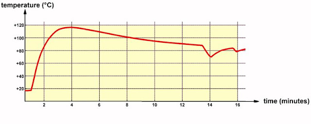
In this measurement, we attached the tip of the type-K thermocouple to the housing of the 2N3773 with heat-conducting paste, set the output voltage to 5.0 V and loaded the power supply with a constant current of 1.8 A. After four minutes, the temperature of the transistor's housing rose to +116 °C! Strangely enough, the temperature starts to drop again afterwards. After about ten minutes, the output voltage of the power supply starts to show strange behaviour, becomes unstable, drops to 4.85 V and the average value of noise and ripple rises to 210 mV. After thirteen minutes, the electronic fuse, which was of course set to 2.0 A, trips, causing the output voltage to go to 0 V. After about ten seconds, the output voltage recovers and the temperature of the transistor rises again. After about two minutes the fuse trips again.
The course of this process is inexplicable without an understanding of the schematic of the device, and can be followed on the graph below, where we have plotted the temperature of the transistor as a function of time.
 |
| The temperature curve of the series transistor. (© 2022 Jos Verstraten) |
The temperature of the transformer
We logged the temperature of the power transformer in an identical manner. We applied the tip of the thermocouple with heat-conducting paste in a gap between one of the secondary windings. Since, with a linear power supply, the power dissipated in the transformer is independent of the output voltage, we only have to perform this measurement once, in this case at 5.0 V and 1.8 A. From the graph below you can see that the transformer heats up to a temperature of +132 °C.
 |
| The temperature curve of the transformer. (© 2022 Jos Verstraten) |
Conclusion
The measured temperatures are far too high! The manufacturer is lying if he claims that you can load this power supply with 2.0 A continuously. Consider this current as the peak value and take a current of 1.0 A as the maximum continuous value. Then the temperatures will be acceptable. The transformer winding gets +62.1 °C, the transistor +83.8 °C. Too hot to touch, but electronically acceptable.
Our conclusion about the 1502DD power supply
It is obvious that we have a lot of criticism on this power supply. The main point of criticism is the way the unit is connected to the mains. No earthed cable, but there is a suggestion on the front panel that the housing is connected to earth. It does have a two-pole mains switch, but only uses a single-pole one.
The second point of criticism is the rather sloppy way in which the various components are connected to each other. The way in which the wires are soldered to the mains switch would give every secondary technical education student a severe failing score.
The third point is that the manufacturer is lying when it claims that this power supply can deliver 2.0 A. Our tests clearly show that 1.0 A continuous current is the maximum you can get out of this power supply, with the remark that 2.0 A as a short peak current is quite feasible.
Finally, most of the specifications given by the manufacturer are exaggerated to say the least! A noise and ripple of only 0.5 mVRMS? Look at our test and smile at so much advertising exaggeration.

Aneng AN87- multimeter

