|
You cannot measure very low resistances accurately with your cheap multimeter. With this module which costs about twenty euros, you can do that. We tested whether this module does what it promises. |
Some necessary background information
Why your multimeter fails
Simply because it has a too low resolution to accurately measure very low resistances. Take the popular Fnirsi S1 as an example. It has a lowest resistance measurement range of 999.9 Ω. If you measure a resistance of 0.47 Ω with this multimeter, the meter will read 000.4 Ω or 000.5 Ω. Good enough for everyday use, but not good enough if you need to know the value of the resistor to two decimals.
Don't forget your test leads!
One source of error in such measurements are your test leads. Set your multimeter to 'measure resistance' and short-circuit your two test leads. We consider the chance that the reading goes to zero to be quite small. The meter will likely read a few tenths of an ohm, the internal resistance of the banana plugs, test leads and test clips. Not a problem if you measure a resistance of 1 kΩ, but a real disaster if you measure resistances of less than 1 Ω. Some more expensive meters allow you to measure 'relatively'. You can automatically subtract this residual resistance from subsequent readings, but the cheaper meters do not have such a function.
The four-wire or kelvin method
There is only one good way to accurately measure such low resistances and that is the kelvin method. Today, all more expensive multimeters use this method. This measurement method is outlined in the figure below. A constant current source is built into the multimeter, which sends via A and B a very constant current Icte through the unknown resistor Rx. Two other test pins C and D are used to measure the voltage generated across the unknown resistance. From ohm's law, the electronics can then derive the value of the resistance in a very simple way. It suffices to divide the voltage drop across the resistor Rx by the constant current Icte.
The advantage of this method is obvious. The resistance of the two leads A and B have no influence because of the constancy of the current Icte. The two test leads C and D that provide the measured voltage to the voltmeter are not passed through by a current. This is because the input resistance of a digital voltmeter is many MΩs.
 |
| The principle of the four-wire or kelvin method. (© 2023 Jos Verstraten) |
The kelvin measuring probe
In practice, measuring pins A and C and B and D are combined in so-called kelvin measuring probes. The picture below shows what these look like. The pliers with gold-plated jaws make good contact with the low resistor to be measured. Two test leads come out of each probe. One is used to supply the constant current to the resistor, the second is used to supply the voltage to the multimeter.
 |
| An example of kelvin probes. (© 2023 Jos Verstraten) |
A low-cost module measures resistances up to 2 Ω
Manufacturer, suppliers and price
Multimeters that measure low resistances using the kelvin method are still quite pricey. If you only need to measure low resistance accurately once in a while, such an investment is not cost-effective. However, an alternative is offered through various channels on AliExpress. A small module of unknown manufacturer measures resistances up to 1,999 mΩ with, at least according to the data, an accuracy of ±[0.5 % + 3 digits]. The module is powered from a DC voltage of 3.4 V to 4.4 V and is supplied with a primitive kelvin probe. You can order this module for around €20.00 from the supplier below:
Searching Google for 'Digital DC Milliohm Meter Range Low 2-Ohm' yields other suppliers.
 |
| The reviewed module in action. (© AliExpress, edit Jos Verstraten) |
The scope of delivery
In addition to the small module and the kelvin probe, you will receive two connection cables and two A4 sheets with a description in Chinese. One of the cables is for connecting the module to the power supply. With the other cable, if you install the module in an enclosure, you can connect the four inputs and outputs of the module to four 4 mm banana plug sockets.
 |
| The scope of delivery of this module. (© 2023 Jos Verstraten) |
The measuring module
The module measures 79 mm by 42 mm by 26 mm and can be mounted in a 76.5 mm by 39.5 mm cutout. On the back are two PCB connectors. A bipolar one is for connecting the power supply, the quadrupole one for connecting the kelvin probe. Both at AliExpress and Banggood you can find a Riden box for around € 15.00 in which you can mount this module. Here is an example:
 |
| Two views of the module. (© 2023 Jos Verstraten) |
The manual
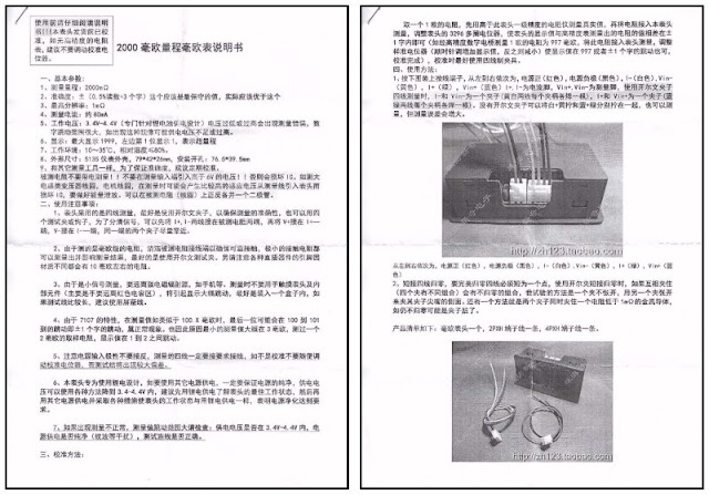
As already written, this module comes with a manual in Chinese only. It never ceases to amaze us how Chinese companies, all ready for international deliveries, still manage to provide only a Chinese manual with their products.

Fortunately, this is not a very big handicap these days. Scan the two sheets of paper with your scanner or take a picture of it with your smartphone. Open 'Google Translate' and choose 'Translate images'. Then choose 'Browsing on your computer' and import the first scanned page. Choose 'Chinese (simplified)' as the language. A few seconds later, a perfectly readable English or Dutch text will appear on your screen.
 |
| The included Chinese manual. (© 2023 Jos Verstraten) |
The electronics in the module
The PCB is clamped into the housing and is easy to remove. In the picture below, you can see both sides of this PCB. The electronics work with an old-fashioned ICL7107CPLZ that was developed by Intersil long ago and is still produced today, for example by Japan's Renesas.
On the PCB is a blue adjustment potentiometer used to calibrate the module. So you should leave that one alone!
 |
The two sides of the PCB. (© 2023 Jos Verstraten) |
The ICL7107CPLZ contains an ADC that operates on the 'dual slope' principle. The principle of analogue-to-digital conversion according to this principle is outlined in the figure below. Built around an operational amplifier IC1 is an integrator with time constant RC that, by means of switch S, integrates the input voltage Uin or a very accurate and stable reference voltage Uref. The Uref must have the opposite polarity to the input voltage. The fundamental property of an integrator is that the output voltage rises or falls linearly depending on the polarity of the input voltage.
The output voltage of the integrator is compared to zero in comparator IC2. For a certain constant time t1, the input voltage Uin is integrated. If you assume that the integration capacitance C was fully discharged, the output voltage of the integrator after time t1 will only be determined by the magnitude of the input voltage. Indeed, all other factors that define the integrator (R, C and t1) are constant. After t1, the electronic switch S is toggled and the reference voltage will start to discharge the capacitor.
It is obvious that the time duration t2 is proportional to the magnitude of the input voltage. Indeed, the discharge current supplied by the reference is constant and the discharge time to zero is otherwise determined only by the magnitude of the voltage after t1. It is therefore sufficient to drive a counter during t2 with pulses of a certain frequency and display the counter contents on a readout after t2. The display then shows the numerical value of the input voltage.
 |
| Operation of the 'dual slope' ADC. (© 2023 Jos Verstraten) |
The colour coding of the connecting wires
The six connecting wires have the following function:
- red: positive pole of the supply voltage
- black: negative pole of the supply voltage
- white: negative pole of the measuring current
- green: positive pole measuring current
- yellow: negative pole of the measuring voltage
- blue: positive pole of the measuring voltage
Testing the module
An introduction...
It is not easy to determine the accuracy of a device that can measure a resistance of 100 mΩ. You obviously need to compare the measurement with the module to this with a reliable meter. Which we have, namely a Fluke 8842A. This also measures according to the kelvin method, of course. However, the two meters must be connected to the resistor in such a way that the contact resistance between the wires of the resistor and the kelvin probes does not play a role. If these contact resistances are different, you will by definition get different readings on both meters!

In order to minimise this risk, we used a file to clean the wires near the resistor body of a number of wire-wound resistors to remove tin and oxidation. Afterwards, we first connected the kelvin probe of this module and then the one of the Fluke as close as possible to the resistor body.
 |
This is how we measured the wire-wound resistors. (© 2023 Jos Verstraten) |
Comparison with the Fluke 8842A
The table below shows the results of our comparative measurements. In the 'percentage deviation' column, we considered the Fluke's measurements to be 100% accurate and calculated the module's percentage deviation from this reference. Except for the lowest value, this does not look bad! These measurements were made with a supply voltage of 4.0 V.
 |
| The accuracy of the module measured. (© 2023 Jos Verstraten) |
The constancy of the measurement current
The kelvin principle demands that measurements are made with a constant current. We measured this current with our ET3255 multimeter and checked the dependence of this current as a function of supply voltage. This is disappointing, see the table below.
 |
| The measuring current as a function of supply voltage. (© 2023 Jos Verstraten) |
Accuracy as a function of supply voltage
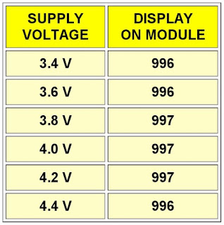
The previous measurement gives rise to the assumption that the accuracy of the measurement depends on the supply voltage. So we measured a resistance of 1.0 Ω with varying supply voltages. As the table below shows, the electronics in the module somehow manage to compensate for the varying measurement current. The measurements are virtually independent of the module's supply voltage.
So that means you can power the module from a 3.7 V lithium-ion battery without any problems. The module draws about 150 mA of current during operation.
 |
| Measurement results as a function of supply voltage. (© 2023 Jos Verstraten) |

