|
With this rather laborious building kit, you construct an LED cube consisting of 512 LEDs. In this three-dimensional structure, light patterns are generated by a microcontroller. |
Introduction to the 3D8 LED cube by ICStation
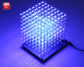
The end result
Finally, a building kit that is not finished in a hurry! Indeed, count on at least ten hours of building fun before you see the end result below on your tinkering table. The 3D8 LED cube consists of a PCB measuring 12.5 cm by 11.0 cm on which you have to solder ten ICs plus some loose parts. Then, on a piece of wood or cardboard, you build eight LED matrices, each consisting of 64 LEDs. Finally, you solder these arrays onto the PCB and together. The device is powered from a 5 V supply and can be equipped with your own programming if desired.
 |
| The end result of this building kit. (© ICStation) |
Suppliers and prices
The building kit was developed by China's ICStation, which specialises in electronics building kits. However, this LED cube is also offered by various vendors on AliExpress, eBay and Amazon for very different prices. We bought ours from ICStation for just $19.56, but there you can only pay via PayPall or credit card. At AliExpress, we saw a price of $17.29, but with a very long delivery time. If you want the building kit delivered quickly, Amazon is an excellent choice with a price of €18.98 and a delivery time of just two days. The kit is available with your choice of red, green or blue LEDs.
The parts provided
The parts you get are represented in the figure below. On the left is the large bag containing the more than five hundred LEDs you need to solder. All ICs are easy-to-solder 'old-fashioned' DILs and come with IC sockets. Apart from these ten chips and the LEDs, this building kit contains very few parts: a few capacitors, a red LED, about ten resistors and a resistor network. The two black long parts are female PCB headers that you should use to make the base into which the LED matrices are soldered.
 |
| The parts supplied. (© 2025 Jos Verstraten) |
The manual
A superb twenty-two-page manual in English can be found on the internet, where every step of the construction is explained by a picture. We assume it was compiled by ICStation, as most building kits supplied by this company are accompanied by such fine manuals. You can download this manual from the link below:
The PCB for the 3D8 LED cube
In the image below, we have joined both sides of the PCB.
 |
| The two sides of the PCB. (© 2025 Jos Verstraten) |
The complete parts list
For some reason, the manual does not contain a parts list. Hence, we publish the complete parts list of this building kit here.
 |
| The complete parts list. (© ICStation) |
The electronics of the 3D8 LED cube
The 512 LEDs are divided into eight matrices, each with eight by eight LEDs. Each matrix is represented by two headers in the diagram below. JP9 is common to all matrices and represents the eight cathode lines of the matrixes. JP1 to JP7 are connected to the eight anode lines of each matrix. Those anode lines are controlled from 74ALS573 ICs. These are octuple type-D flip-flops with tri-state outputs. Through its P00 to P07 outputs, the microcontroller provides the data to drive the anodes of the LEDs to the D inputs of these flip-flop's. The Q outputs are directly connected to the total 64 anode lines of the eight matrices.
The common cathode lines are pulled to ground via 220 Ω resistors and a ULN2803. This is an octuple darlington that can sink 500 mA per output to ground. The inputs of this IC are controlled from the P10 to P17 lines of the microcontroller. That is an STC12C5A60S2 programmed by the assembler of the building kit.
 |
| The schematic of the 3D8 LED cube. (© ICStation) |
Assembling the main PCB
Free the contacts from the female PCB headers
The first step is to free the contacts from the female PCB headers. The best way to do this is with a fine cutting tool. By cutting through the plastic at the right place, you can peel off the metal contacts from the header. Take care not to bend these contacts in the process, as the solder pin will break off very quickly if you bend it.
 |
| The first step is to free the pins from the headers. (© 2025 Jos Verstraten) |
Next, you need to attach these contacts to the solder side of the PCB and in those places where there is a circle drawn around the pad. In fact, the holes in the PCB are a bit too big, so the contacts will wobble a bit. Still, try to put the pins on the PCB as straight as possible. Of course, you solder on the component side of the PCB.
The contacts marked C1 to C8 will later form the common cathode lines of the LED matrices.
 |
| Soldering the header contacts on the PCB. (© 2025 Jos Verstraten) |
Soldering the components onto the PCB
Solder onto the underside of the PCB:
- Eight resistors R3 - R10 of 470 Ω
- Two ceramic capacitors C2 and C3 of 22 pF
- The crystal Y1 of 12 MHz
- The resistor network A09-103 with the text facing the microcontroller socket
- Eight IC sockets with 20 pins (note the position)
- One IC socket with 18 pins (note the position)
- One IC socket with 40 pins (note the position)
- Mount the four copper spacers with bolts
 |
| The components onto the underside of the PCB. (© 2025 Jos Verstraten) |
Solder on the top of the PCB:
- Two resistors R1 and R2 of 4.7 kΩ
- The red LED (note polarity)
- Two electrolytic capacitors C1 and C4 of 10 μF (note polarity)
- The pushbutton switch S1
- The power connector
The places for the jumper J3 and the two switches S2 and S3 remain open. These parts are not supplied and are only of interest to advanced hobbyists who want to program the microcontroller themselves.
 |
| The components on the top of the PCB. (© 2025 Jos Verstraten) |
Finally, mount the ten ICs in their sockets. Of course, pay close attention to the position of these components.
Construction and mounting of the LED matrices
The schematic of the LED matrices
The figure below shows the schematic of the LED matrices. It consists of eight horizontal and eight vertical lines between which the 64 LEDs are fitted. The idea is to reconstruct that schematic using only the connecting wires of the LEDs for the interconnections.
 |
The schematic of the LED matrices. (© 2025 Jos Verstraten) |
An aide to the construction
To construct the matrices, you must first provide a wooden board with 64 holes of 3.0 mm diameter. Those holes should be exactly 1.5 cm apart and, of course, in an eight-by-eight matrix.
 |
| The wooden board in which you mount the LED matrices. (© 2025 Jos Verstraten) |
Preparing the LEDs
Take an LED in your left hand with the longest wire (the anode) to the right. Clamp this connecting wire in flat nose pliers with your right hand, then bend the wire backwards at a 90° angle with your left hand. Repeat for seven other LEDs. Of course, the bend in the wires should be in the same place for all LEDs.
 |
| Bending the anode wire of the LEDs. (© 2025 Jos Verstraten) |
Soldering the anode wires of the matrix
Now push the eight LEDs into a row of holes in the wooden board. Start on the right and work to the left, making sure that the anode wire of the left LED is always in front of the one of the right LED. Using very little tin, solder the two anode wires together. Make sure, of course, that the anode wires do not make contact with the cathode wires.
 |
| Soldering one anode row of the diode matrix. (© 2025 Jos Verstraten) |
Repeat with 56 LEDs for the remaining seven anode lines.
 |
| The eight anode lines of the diode matrix are ready. (© 2025 Jos Verstraten) |
Soldering the cathode wires of the matrix
Place a pencil along the cathode side of the LEDs and bend the cathode wires of the LEDs 90° backwards.
 |
| Bending the cathode wires of the LEDs. (© 2025 Jos Verstraten) |
Now solder together the cathode wires of the LEDs column by column. Make sure there is a distance of a few millimeters between the anode lines and the cathode lines everywhere.
 |
| One of the eight LED matrices is ready! (© 2025 Jos Verstraten) |
Assembling and testing the first matrix
Note
It is absolutely essential that you use the first diode matrix to test whether the circuit works. If it does not work, you still have the opportunity now to get to all the soldering on the PCB and correct any bad soldering or forgotten soldering.
Soldering the eight anode lines
Carefully remove your first matrix from the wooden board. Make sure all the LEDs remain neatly in horizontal and vertical lines. Now solder the eight anode lines onto the contacts of the female PCB headers that are on the second row, i.e. below the row notated C1 to C8. Also note the position of the LEDs in the picture below.
 |
| Soldering the eight anode lines on the PCB. (© 2025 Jos Verstraten) |
Soldering the eight cathode lines
Turn the PCB over and connect the eight cathode lines to contacts C1 to C8 of the female PCB headers. For this, you can use pieces of the flexible mounting wire supplied with the kit.
 |
| Soldering the eight cathode lines on the PCB. (© 2025 Jos Verstraten) |
Testing the circuit
Using the supplied power cable, connect the PCB to a 5 V mains power supply and press the switch on the PCB. The video below will give you an impression of what you should see.
The final assembly
Constructing the seven remaining matrices
It should be clear what you need to do next: one by one, construct the remaining seven matrices as described and solder them onto the PCB with the anode lines.

Connecting the cathode lines
After you have soldered the second matrix onto the PCB, use flat nose pliers to bend the eight free ends of the cathode wires of the first matrix at a 90° angle to the second matrix and solder them to the cathode wires of this matrix.
Test each time
Test the circuit after soldering each new matrix. You can then still easily detect and repair faulty LEDs or short circuits in the new matrix.
The end result
The figure below shows the end result of your hard work. Your 3D8 LED cube is ready!
 |
| The 3D8 LED cube is ready! (© ICStation) |
3D8 LED-cube kit