
|
With this € 15.00 kit, you can measure frequencies up to a maximum of 50 MHz with a sensitivity of 75 mVrms. By adding or subtracting an intermediate frequency to the measurement, you can measure the frequency of a received radio station. |
Introduction to this 50 MHz frequency meter kit
Manufacturer, suppliers, price
According to the information on the PCB, this kit is developed by 'EZM Electronics Studio'. However, sometimes 'ECM Electronics Studio' is mentioned. Apparently this company does not have its own website. The kit proves to be very popular and can be purchased from at least a dozen providers via the well-known internet channels such as Banggood and AliExpress. However, you should keep in mind that there are various versions in circulation that differ from each other in detail. For example, there is a version where the display consists of three seven-segment indicators and another version where only one indicator provides the five digits.
We bought a package with order number 19.16.521 from Banggood for the price of € 13.48. Various providers apparently offer the package cheaper via AliExpress, but then you have to count on fairly high shipping costs, bringing the total amount to about € 17.00.
Credits
As often happens with Chinese kits, the circuit has been 'copied' from an earlier design. According to one of our readers, this kit (and many other similar frequency counters from AliExpress/Banggood) uses the code of Wolfgang 'Wolf' Büscher, DL4YHF in the programmed PIC. The original is at:
What can this 50 MHz frequency counter do?
First, of course, measure and display the frequency of the signal you connect to the BNC input. The device has a specified sensitivity of 20 mV for signals with frequencies between 1 Hz and 100 kHz. At 50 MHz, the maximum guaranteed frequency to be measured, the sensitivity decreases to 75 mV. These are of course very good values, but we will test them after the construction of our kit.
Secondly, with this device you can digitally measure the frequency to which a superhet receiver is tuned. This may require some explanation, which you will find in the next section.
Measuring the tuning frequency of a superheterodyne receiver
Analog radio broadcasts in the frequency ranges of long, medium and short wave are always received with so-called superheterodyne receivers. A superheterodyne radio receiver, called superhet for short, is a device in which the transmitter signal is mixed with a sine wave signal generated by the local oscillator (VFO). The frequency of that oscillator can be varied by turning the tuning knob of the receiver. This mixing produces signals with the sum and difference frequencies of both signals. These signals are applied to the intermediate frequency amplifier which has a very narrow passband around a certain intermediate frequency IF.
An example. The intermediate frequency of a particular superhet is 10.7 MHz. The local oscillator is set to 100 MHz. Only a station broadcasting on a carrier of 89.3 MHz will generate a difference signal with a frequency of 10.7 MHz. All other transmitters generate other differential frequencies and are not amplified by the intermediate frequency amplifier and therefore not received.
If you want to know the frequency of a received station, it is therefore sufficient to measure the frequency of the local oscillator and subtract the intermediate frequency from it. The software of this 50 MHz frequency meter has the ability to perform this operation automatically, allowing you to use this device as a digital indicator of the tuning frequency of any superheterodyne receiver (within the 50 MHz measuring range of the device, of course).
Five frequently used intermediate frequencies are stored in memory. All you need to do is connect the input of the meter to the output of the local oscillator and set the offset to the intermediate frequency of the receiver.

The result of the construction of this kit
The photo below shows what the result of this kit looks like. The frequency meter is mounted on a PCB of 80 mm by 63 mm. A second PCB of 80 mm by 35 mm is mounted on this PCB. On this PCB there is only the display. At the bottom right of the first PCB you see the BNC connector for the input signal. On the left is the power connector for connecting the PCB to a supply voltage between 7.0 Vdc and 9.0 Vdc. The circuit has only two control buttons. On the left you see an ON/OFF push button. On the right is a small PROG push button with which you program the meter.
The specifications of the 50 MHz frequency meter
According to the manufacturer, the circuit complies with the following specifications:
- Measuring range: 1 Hz ~ 50 MHz
- Resolution: 4 or 5 digits
- Input impedance: 1.1 MΩ // 10 pF
- Input sensitivity 1 Hz ~ 100 kHz: 20 mVrms
- Input sensitivity 100 kHz ~ 20 MHz: 35 mVrms
- Input sensitivity 20 MHz ~ 50 MHz: 75 mVrms
- Supply voltage: 7.0 Vdc ~ 9.0 Vdc
- Supply current: 50 mA
- Automatic range switching: yes
- Automatic gate time switching: yes
- Automatic measuring range indication: yes
- Automatic power-safe: yes, after 15 seconds
- Dimensions: 9.2 cm x 6.3 cm x 2.3 cm
- Weight: 60 g
The delivered components
The photo below shows the scope of delivery of this kit. What is striking is that one SMD component is included, an LM1117-5V. That could have been different, because this voltage stabilizer is also available in the 'old-fashioned' housing. For a kit that is clearly intended for the novice hobbyist, soldering an SMD may be a bit too much!
The main PCB
Both sides of the main PCB are shown in the figure below.
The display PCB
We also put this PCB under the scanner twice.
The manual
Our kit included one sheet of A4 with a component list on one side and the component layout of both PCBs on the other. Not a single word about the operation of the device and the function of the push button! Fortunately, there is on the internet some more information about this circuit. To make it easy for you, we have collected them in one PDF file:
➡ 50MHz_Frequency_counter_Manual.pdf
The power supply
The power supply is extremely simple and its task is to reduce the 7.0 Vdc to 9.0 Vdc that you are allowed to connect to the PCB to 5 Vdc. This is done with an LM1117-5V chip, see the diagram below.
The input amplifier
The input amplifier is by far the most important circuit of any digital frequency counter. After all, it determines the frequency range, sensitivity and input impedance that can be achieved in practice.
In this circuit, a very simple circuit has been chosen, see the figure below. The input signal is applied to the gate of FET Q2 via the resistor attenuator R10-R11. Those resistors are not intended to attenuate the signal, because that would reduce the sensitivity. They are intended to fix the input impedance to a constant value and to protect the circuit against too high input voltages. If the voltage on the gate becomes greater than +0.65 V or lower than -0.65 V, one of the diodes D5-D6 conducts and the rest of the input voltage drops across the resistor R10. Simple yet effective circuit protection! In order to also capacitively balance the voltage divider R10-R11, a small capacitor C2 has been applied across R10.
The FET Q2 is wired as a source follower. This circuit is characterized by a very high input resistance at the gate and a very low output resistance at the source. The signal on the source is capacitively coupled to the second stage. That is an inverting single-stage amplifier Q3 with a fairly large gain and a feedback from the collector to the base. The signal is taken from the collector of Q3. Because 'OUT' goes to an input of the microcontroller, certain requirements are imposed on the voltage at the collector of Q3. We will come back to this later.
The frequency meter around the microcontroller
The diagram below shows the digital part of the meter. The heart of this circuit is a PIC16F628A microcontroller (U1). The input signal is applied to input RA4. The outputs RB control the segments of the display, the outputs RA the digits. Since the PIC16F628A only has six RA pins and all six are in use, something had to be invented to control the fifth display. Hence the circuitry around Q1, which switches the fifth display Dig5 to ground only when the four signals on RA0, RA1, RA2 and RA3 are 'H'. The three diodes then are blocking and resistor R9 drives transistor Q1 into conduction.
The circuit works with a 20 MHz crystal. Because the accuracy of the frequency of this crystal determines the accuracy of the readout, the possibility is built in to adjust the frequency of the crystal to a limited extent. That is possible with the trimmer C7.
Component drawing
Because the component drawing in the manual is rather vague, we have graphically edited it into a clearly legible 'silk screen'.
The soldering of the main PCB
The most convenient soldering order of the main board is:
The soldering of the display PCB
You only need to solder two parts to that PCB:
Final assembly
Finally, you must insert the display PCB into the main PCB and screw it on at the bottom with the two supplied screws.
Startup
After connecting a suitable power supply with an output voltage between 7.0 Vdc and 9.0 Vdc and pressing the ON/OFF switch SW2, all displays light up completely for a moment. Afterwards, the device is ready to measure the frequency of the input signal.
The various ranges
The device has eight measuring ranges that are selected automatically:
- 0.009 Hz (decimal point blinks)
- 0.099 Hz (decimal point blinks)
- 0.999 Hz (decimal point blinks)
- 9.999 kHz (decimal point blinks)
- 99.999 kHz (decimal point blinks)
- 999.99 kHz (decimal point blinks)
- 9.9999 MHz (decimal point does not blink)
- 99.999 MHz (decimal point does not blink)
To make clear the difference between measuring kHz and measuring MHz, the decimal point is flashed in the first case. At the lowest measuring ranges, the right-most display is turned off. This has to do with the gate time, which is a maximum of one second, and as a result of which the resolution in the lowest ranges is only 1 Hz.
The programming push button
After briefly pressing the push button 'PROG' (SW1), the text 'Prog' appears on the display. By pressing this button a number of times you will go through all the options of the program:
Activating the selected option
You activate an option by pressing the 'PROG' button until the display starts flashing.

Programming the offset frequency
That is quite simple.
1 - Press the button until 'Prog' appears.
2 - Press the button repeatedly until 'Table' appears.
3 - Long press the button until 'Table' starts flashing.
4 - Now select the intermediate frequency.
5 - Press the button until the display starts flashing.
6 - Selects 'Add' or 'Sub'.
7 - Press the button again until the display starts flashing.
The selected intermediate frequency is now added or subtracted from the input frequency.
Our frequency reference
To test the accuracy of a frequency counter, you must of course have an HF sine wave generator that supplies a very accurate frequency. We are the lucky owners of a Marconi TF2015 high frequency sine wave generator with a TF2171 Digital Synchroniser. The TF2171 internally has an extremely stable frequency standard of 5 MHz and a lot of digital frequency dividers, with which you can set the frequency of the TF2015 to 100 Hz by means of seven rotary switches. Both devices are in a feedback system that regulates the frequency generated by the TF2015 via a PLL. In this way, the accuracy and stability of the frequency is guaranteed within ±1/10,000,000 parts.
The accuracy
Even without turning the trimmer C7, this kit provides an accurate reading. We test at two frequencies:
- Setting on the TF2015 10,0000 MHz: measured 10,001 MHz
- Setting on the TF2015 50,0000 MHz: measured 50,006 MHz
By turning the trimmer (do not use a metal screwdriver!) the accuracy could be increased slightly:
- Setting on the TF2015 10,0000 MHz: measured 10,000 MHz
- Setting on the TF2015 50,0000 MHz: measured 50,003 MHz
Maximum frequency to be measured
Our HF generator delivers a voltage of maximum 165.0 mVrms. With this signal, our kit still measures up to 79.0000 MHz. At 80.0000 MHz on the input it goes wrong, the meter measures 79.803 MHz. At higher frequencies, our kit completely fails, the measured values are tens of MHz too low.
The sensitivity
Sensitivity is the rms voltage that you must apply to the input to get a stable and exact frequency reading. The table below shows the measurement results. You can see that these cheap frequency counter perform quite well! Our kit does better than the specs promise.

(Banggood sponsor ad)
50 MHz frequency counter kit
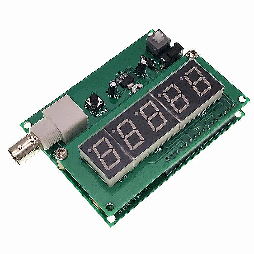
The photo below shows what the result of this kit looks like. The frequency meter is mounted on a PCB of 80 mm by 63 mm. A second PCB of 80 mm by 35 mm is mounted on this PCB. On this PCB there is only the display. At the bottom right of the first PCB you see the BNC connector for the input signal. On the left is the power connector for connecting the PCB to a supply voltage between 7.0 Vdc and 9.0 Vdc. The circuit has only two control buttons. On the left you see an ON/OFF push button. On the right is a small PROG push button with which you program the meter.
 |
| The result of building this kit.(© Banggood) |
The specifications of the 50 MHz frequency meter
According to the manufacturer, the circuit complies with the following specifications:
- Measuring range: 1 Hz ~ 50 MHz
- Resolution: 4 or 5 digits
- Input impedance: 1.1 MΩ // 10 pF
- Input sensitivity 1 Hz ~ 100 kHz: 20 mVrms
- Input sensitivity 100 kHz ~ 20 MHz: 35 mVrms
- Input sensitivity 20 MHz ~ 50 MHz: 75 mVrms
- Supply voltage: 7.0 Vdc ~ 9.0 Vdc
- Supply current: 50 mA
- Automatic range switching: yes
- Automatic gate time switching: yes
- Automatic measuring range indication: yes
- Automatic power-safe: yes, after 15 seconds
- Dimensions: 9.2 cm x 6.3 cm x 2.3 cm
- Weight: 60 g
The delivered components
The photo below shows the scope of delivery of this kit. What is striking is that one SMD component is included, an LM1117-5V. That could have been different, because this voltage stabilizer is also available in the 'old-fashioned' housing. For a kit that is clearly intended for the novice hobbyist, soldering an SMD may be a bit too much!
 |
The supplied components. (© 2022 Jos Verstraten) |
The main PCB
Both sides of the main PCB are shown in the figure below.
 |
Both sides of the main PCB. (© 2022 Jos Verstraten) |
The display PCB
We also put this PCB under the scanner twice.
 |
| Both sides of the display PCB. (© 2022 Jos Verstraten) |
The manual
Our kit included one sheet of A4 with a component list on one side and the component layout of both PCBs on the other. Not a single word about the operation of the device and the function of the push button! Fortunately, there is on the internet some more information about this circuit. To make it easy for you, we have collected them in one PDF file:
➡ 50MHz_Frequency_counter_Manual.pdf
The electronics in this 50 MHz frequency counter
The power supply
The power supply is extremely simple and its task is to reduce the 7.0 Vdc to 9.0 Vdc that you are allowed to connect to the PCB to 5 Vdc. This is done with an LM1117-5V chip, see the diagram below.
 |
The power supply of the circuit. (© 2022 Jos Verstraten) |
The input amplifier
The input amplifier is by far the most important circuit of any digital frequency counter. After all, it determines the frequency range, sensitivity and input impedance that can be achieved in practice.
In this circuit, a very simple circuit has been chosen, see the figure below. The input signal is applied to the gate of FET Q2 via the resistor attenuator R10-R11. Those resistors are not intended to attenuate the signal, because that would reduce the sensitivity. They are intended to fix the input impedance to a constant value and to protect the circuit against too high input voltages. If the voltage on the gate becomes greater than +0.65 V or lower than -0.65 V, one of the diodes D5-D6 conducts and the rest of the input voltage drops across the resistor R10. Simple yet effective circuit protection! In order to also capacitively balance the voltage divider R10-R11, a small capacitor C2 has been applied across R10.
The FET Q2 is wired as a source follower. This circuit is characterized by a very high input resistance at the gate and a very low output resistance at the source. The signal on the source is capacitively coupled to the second stage. That is an inverting single-stage amplifier Q3 with a fairly large gain and a feedback from the collector to the base. The signal is taken from the collector of Q3. Because 'OUT' goes to an input of the microcontroller, certain requirements are imposed on the voltage at the collector of Q3. We will come back to this later.
 |
| The input amplifier of the circuit. (© 2022 Jos Verstraten) |
The frequency meter around the microcontroller
The diagram below shows the digital part of the meter. The heart of this circuit is a PIC16F628A microcontroller (U1). The input signal is applied to input RA4. The outputs RB control the segments of the display, the outputs RA the digits. Since the PIC16F628A only has six RA pins and all six are in use, something had to be invented to control the fifth display. Hence the circuitry around Q1, which switches the fifth display Dig5 to ground only when the four signals on RA0, RA1, RA2 and RA3 are 'H'. The three diodes then are blocking and resistor R9 drives transistor Q1 into conduction.
The circuit works with a 20 MHz crystal. Because the accuracy of the frequency of this crystal determines the accuracy of the readout, the possibility is built in to adjust the frequency of the crystal to a limited extent. That is possible with the trimmer C7.
 |
| The circuit around the microcontroller PIC16F628A. (© 2022 Jos Verstraten) |
The construction of the 50 MHz frequency counter
Component drawing
Because the component drawing in the manual is rather vague, we have graphically edited it into a clearly legible 'silk screen'.
 |
| A clear drawing for the assembly of the main PCB. (© 2022 Jos Verstraten) |
The soldering of the main PCB
The most convenient soldering order of the main board is:
- The only SMD component, the LM1117-5V.
- The six 1N4148 diodes. Note that the diode D6 has a different cathode position than the other five.
- The 1N5819 diode D7.
- The fifteen resistors. Something weird is going on with R13. The delivered value apparently depends on the batch to which your kit belongs. So it is best to solder all the other resistors first and the one that remains is this resistor. In the package delivered to us, the value was equal to 56 kΩ. In addition, the value of this resistor determines the voltage at the junction between R13, R14 and the collector of Q3. This point is marked 'TP' in the drawing above. The DC voltage at this point should be approximately equal to 2.2 V. If this is not the case with your kit, adjust the value of R13 until it is.
- The capacitors C14 and C15, with a value of 22 pF (code 22).
- The capacitors C3 and C5 of 100 nF (code 104).
- The 100 pF capacitor C2 (code 101).
- The capacitor C1 which has a value of 100 nF on the PCB, but is stated in the manual as 470 nF. This value is also supplied with our package (code 474). That is the input capacitor, so the higher the value of this capacitor, the lower the measurable frequency becomes.
- The crystal X1 of 20 MHz. Make sure that this 'floats' a millimeter above the surface of the PCB so that the metal housing cannot cause a short circuit on the PCB.
- The capacitor trimmer C7 with an adjustable value from 5 pF to 20 pF, with which you can slightly vary the clock frequency of the microcontroller and thus calibrate the meter.
- The IC socket.
- The three capacitors C4, C6 and C8. Note the plus and the minus!
- The PROG switch.
- The power connector, unfortunately, they have not opted for a standard 5.5 mm x 2.1 mm version, but one that is much smaller (3.5 mm x 1.35 mm). Hopefully you have a male connector that fits in here.
- The 16-pin print header.
- The ON/OFF switch.
- The BNC connector.
- The two brass spacers.
 |
| The fully assembled main board. (© 2022 Jos Verstraten) |
The soldering of the display PCB
You only need to solder two parts to that PCB:
- The 16-pin PCB connector, which you mount on the underside of the PCB (where the 'Made in China' logo is) with the shortest pins through the print. You solder it on the other side.
- The display. Strangely enough, the part delivered to us has one less pin than there are holes in the PCB. Pay close attention to the position of the decimal points! These should be at the bottom of the PCB, see the photo below.
 |
| The fully assembled display PCB. (© 2022 Jos Verstraten) |
Final assembly
Finally, you must insert the display PCB into the main PCB and screw it on at the bottom with the two supplied screws.
 |
| The two PCBs attached to each other. (© 2022 Jos Verstraten) |
Working with this 50 MHz frequency counter
Startup
After connecting a suitable power supply with an output voltage between 7.0 Vdc and 9.0 Vdc and pressing the ON/OFF switch SW2, all displays light up completely for a moment. Afterwards, the device is ready to measure the frequency of the input signal.
The various ranges
The device has eight measuring ranges that are selected automatically:
- 0.009 Hz (decimal point blinks)
- 0.099 Hz (decimal point blinks)
- 0.999 Hz (decimal point blinks)
- 9.999 kHz (decimal point blinks)
- 99.999 kHz (decimal point blinks)
- 999.99 kHz (decimal point blinks)
- 9.9999 MHz (decimal point does not blink)
- 99.999 MHz (decimal point does not blink)
To make clear the difference between measuring kHz and measuring MHz, the decimal point is flashed in the first case. At the lowest measuring ranges, the right-most display is turned off. This has to do with the gate time, which is a maximum of one second, and as a result of which the resolution in the lowest ranges is only 1 Hz.
The programming push button
After briefly pressing the push button 'PROG' (SW1), the text 'Prog' appears on the display. By pressing this button a number of times you will go through all the options of the program:
- Quit:
You exit the programming mode and go back to measuring the frequency. - NoPSU:
This option enables the automatic power safe. - Add:
Adds the selected intermediate frequency (read more) to the measurement results. - Sub:
Subtracts the selected intermediate frequency from the measurement results. - Zero:
The frequency offset is reset to zero, the meter again measures the true frequency of the input signal. - Table:
You can select the intermediate frequency to add to or subtract from the measurement result: 455 kHz ~ 3.999 MHz ~ 4.1943 MHz ~ 4.4336 MHz ~ 10.700 MHz.
Activating the selected option
You activate an option by pressing the 'PROG' button until the display starts flashing.
Programming the offset frequency
That is quite simple.
1 - Press the button until 'Prog' appears.
2 - Press the button repeatedly until 'Table' appears.
3 - Long press the button until 'Table' starts flashing.
4 - Now select the intermediate frequency.
5 - Press the button until the display starts flashing.
6 - Selects 'Add' or 'Sub'.
7 - Press the button again until the display starts flashing.
The selected intermediate frequency is now added or subtracted from the input frequency.
A few tests on the 50 MHz frequency counter
Our frequency reference
To test the accuracy of a frequency counter, you must of course have an HF sine wave generator that supplies a very accurate frequency. We are the lucky owners of a Marconi TF2015 high frequency sine wave generator with a TF2171 Digital Synchroniser. The TF2171 internally has an extremely stable frequency standard of 5 MHz and a lot of digital frequency dividers, with which you can set the frequency of the TF2015 to 100 Hz by means of seven rotary switches. Both devices are in a feedback system that regulates the frequency generated by the TF2015 via a PLL. In this way, the accuracy and stability of the frequency is guaranteed within ±1/10,000,000 parts.
 |
| The TF2015/TF2171 combination from Marconi. (© 2022 Jos Verstraten) |
The accuracy
Even without turning the trimmer C7, this kit provides an accurate reading. We test at two frequencies:
- Setting on the TF2015 10,0000 MHz: measured 10,001 MHz
- Setting on the TF2015 50,0000 MHz: measured 50,006 MHz
By turning the trimmer (do not use a metal screwdriver!) the accuracy could be increased slightly:
- Setting on the TF2015 10,0000 MHz: measured 10,000 MHz
- Setting on the TF2015 50,0000 MHz: measured 50,003 MHz
Maximum frequency to be measured
Our HF generator delivers a voltage of maximum 165.0 mVrms. With this signal, our kit still measures up to 79.0000 MHz. At 80.0000 MHz on the input it goes wrong, the meter measures 79.803 MHz. At higher frequencies, our kit completely fails, the measured values are tens of MHz too low.
The sensitivity
Sensitivity is the rms voltage that you must apply to the input to get a stable and exact frequency reading. The table below shows the measurement results. You can see that these cheap frequency counter perform quite well! Our kit does better than the specs promise.
 |
| The sensitivity as a function of the frequency. (© 2022 Jos Verstraten) |
50 MHz frequency counter kit