Introduction to the Aneng V01A multimeter
The delivery of the meter
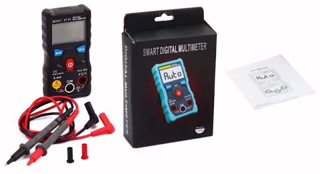
Of course you can only order this device for the mentioned price directly in China. This multimeter is sloppily packaged in a sheet of bubble wrap, delivered in a neat cardboard box. This box contains the meter, two measuring leads with a length of 70 cm and an excellent English manual. The meter comes with two mounted 1.5 V type AAA batteries and is therefore ready for use. The two test leads are well insulated and have sharp points. The chance that you will accidentally come into contact with the measuring voltage with these test leads is zero.
The meter is fitted in a sturdy rubber casing that fits well in your hand and the device is adequately protected against bumps and falls. At the back there is a fold-out support, with which you can place the meter at an easily readable angle on your workbench.
 |
| The way in which the V01A is delivered is not to be criticized. (© 2019 Jos Verstraten) |
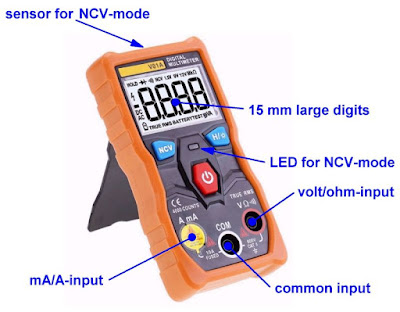
The V01A has only three push buttons:
- ON/OFF
Pressing this red button for more than two seconds will turn the meter on. A second press of this button will immediately turn the meter off. When the meter is switched on, the text 'Auto' will appear on the display until you connect something to the meter. - NCV
By constantly pressing this button you will enter the so-called 'Non Contact Voltage' mode. The meter is then sensitive to the electromagnetic fields of alternating voltages and this way you can find wires in walls, at least that is the intention (read more). - H/☼
Pressing this button freezes the display. Pressing this button for longer than two seconds switches the white LED on the back of the meter on. However, you should not expect a lot of light!
The input for current measurements is shielded with a sticker stating that measurements of more than 2 A should only take three seconds. When measuring currents, the buzzer and the LED are activated every second, so that you are warned that you may not connect the two test leads to a voltage source, but must connect them in series with a circuit.
 |
| The three control keys of the Aneng V01A. (© 2019 Jos Verstraten) |
All components are of course on one print, which fills the entire interior of the meter. We borrowed a photo from our fellow testers at Lygte-info (https://lygte-info.dk/review/DMMAnengV01A%20UK.html), who took the trouble to dismantle one copy of the V01A to be able to take a picture of the print.
A striking feature is the internal fuse of 10 A in the current measuring circuit, which according to the text on the circuit board can withstand a maximum of 250 V. However, the V01A is offered by Aneng as a Cat II meter, to which you can connect 600 V. This fuse does not have standard dimensions, replacement is therefore not easy.
A second feature that strikes you is that the voltage divider for the voltage ranges of the meter is equipped with seven large resistors, which are also in series. The maximum voltage that you can connect to the meter (600 V) is therefore distributed over these parts, electrical breakthrough can therefore not take place. To the left of the resistors of the input divider you can see a small chip, IC2. This is a SGM3157 analog switch that probably has something to do with the automatic switching of the measuring range.
 |
| The internal electronics of Aneng V01A. (© 2018 Lygte-info / © 2019 Jos Verstraten) |
What is immediately noticeable is the small current sensor PCB above the mA/A input. The meter automatically switches from voltage to current measurement when you plug one of the test leads into the A/mA input. To achieve this, the A/mA input is composed of two 180° curved metal plates, which do not make contact. However, if you insert a banana plug into this input, both parts are of course connected via the plug. This small PCB detects this and switches the internal electronics from voltage to current measurement.

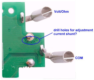
The current is measured by measuring the voltage drop over the 'resistor' R22, a current shunt that has been soldered sloppily to the PCB. There are no adjustment potentiometers on the PCB. So the question remains how the current measuring range is calibrated. Well, after some thought about the function of some strange holes in the PCB, we came to the conclusion that the resistance of this shunt is adjusted by drilling holes in the copper plane that connects R22 to the rest of the PCB. The more holes, the higher the resistance of the copper layer becomes.
 |
| The holes in the PCB which, in our opinion, adjust the current shunt. (© 2019 Jos Verstraten) |
According to the manufacturer, this multimeter meets the following specifications:
- Readout: 4000 max. for voltage and resistance
- Readout: 9999 max. for current
- Measurement frequency: 3 measurements per second
- Minimum input voltage required: 0.8 V typical
- DC voltage range: 4.000 V ~ 40.00 V ~ 400.0 V ~ 600 V
- DC voltage accuracy: ±(0.5 % + 3 digits)
- AC voltage range: 4.000 V ~ 40.00 V ~ 400.0 V ~ 600 V
- AC voltage accuracy: ±(1.0 % + 3 digits)
- Measuring method AC voltage: RMS measurement
- Input resistance voltage ranges: not specified
- DC current range: 999.9 mA ~ 9.999 A
- DC current accuracy: ±(1.0 % + 3 digits)
- AC current range: 999.9 mA ~ 9.999 A
- AC current accuracy: ±(1.0 % + 3 digits)
- Frequency range: 40 Hz ~ 1 kHz
- Resistance range: 4.000 kΩ ~ 40.00 kΩ ~ 400.0 kΩ ~ 4.000 MΩ ~ 40.00 MΩ
- Resistance range accuracy: ±(0.5 % + 3 digits)
- Resistance range 40.00 MΩ accuracy: ±(1.5 % + 3 digits)
- Continuity measuring range: 50 Ω max.
- Power supply: 2 x 1.5 V type AAA battery (included)
- Power consumption standby: 0.2 μA
- Current consumption when measuring: 1.5 mA
- Dimensions: 120 mm x 60 mm x 27 mm
- Weight: 132 g
A few remarks about these specifications
It seems strange to find a minimum input voltage in the specifications of a multimeter. This has everything to do with the fully automatic switching. The electronics of the V01A only interpret an input as a voltage to be measured if you apply a DC or AC voltage of at least 0.8 V. If there is a lower voltage at the input, the display still shows 'Auto'. This is quite a high threshold, because it means that you cannot measure conductive voltages of diodes, for example!
If you put a resistance of less than 50 Ω between the terminals, the V01A automatically switches to the continuity mode, the LED lights up and the buzzer is activated.
The Aneng V01A multimeter on the test bench
Measurement of direct voltages
As a first test, we connected the Aneng V01A to our reference voltage source, which supplies DC voltages of 2.500 V ~ 5.000 V ~ 7.500 V ~ 10.000 V. As the table below shows, the measurement results are convincing. With a maximum deviation of 0.32%, our test sample appears to perform better than the specifications suggest.
 |
| The Aneng V01A connected to our reference voltage source. (© 2019 Jos Verstraten) |
 |
| The accuracy of DC voltage measurements. (© 2019 Jos Verstraten) |
In the absence of variac, we have to use the output voltage of our digitally adjustable function generator. The table below shows the measurement results for a sine wave voltage with a frequency of 50 Hz. Again, the lower measurement limit is 0.8 V.
 |
| The accuracy of AC voltage measurements. (© 2019 Jos Verstraten) |
Strangely enough, this parameter is not specified by the manufacturer. Most multimeters have a resistance of 10 MΩ when measuring voltages, so that you have the least possible influence on the voltage distribution in the circuit in which you measure. Not specifying this parameter in the specifications made us curious. Fortunately, this parameter is easy to measure. Connect an adjustable voltage to the meter until it indicates exactly 20.00 V, for example. Then set a very accurate resistor of 100 kΩ is series with one of the test leads. The meter will now indicate a lower voltage and from the voltage difference you can calculate the internal resistance of the meter. To our astonishment, two measurements (20.00 Vdc and 2.000 Vdc) revealed an input resistance of only 277 kΩ! When measuring the 230 V mains voltage, an input resistance of 275 kΩ was calculated in the same way.
As a result, the V01A becomes completely unreliable when measuring in high impedance circuits!

Test of the RMS value of signal shapes
According to the specifications, the V01A calculates the RMS value of the applied AC voltages. The RMS value of an AC voltage is equal to a DC voltage that generates the same thermal power in a load as the considered RMS value. We have a good professional multimeter which calculate the RMS value of various signal shapes very accurate. We have supplied the V01A with various signal shapes with a frequency of 50 Hz and set the amplitude of the function generator so that our reference meter in all cases indicated an RMS value of 3.000 V. These results are again excellent, see the table below.
 |
| The measured RMS value of different signal shapes. (© 2019 Jos Verstraten) |
According to the specifications, the meter should measure accurately from 40 Hz to 1 kHz. Unfortunately there is no indication of what is understood by 'accurately'. In the graph below we have tested this feature of the V01A. And again, it's getting monotonous, we were very enthusiastic about the performance of this cheap meter. As a reference, the reading on the V01A at 50 Hz was set to 3.000 Vrms and afterwards the frequency was varied at constant output voltage of the generator. The conclusion is that you can trust this meter between 30 Hz and 1 kHz.
 |
| The frequency response of the Aneng V01A. (© 2019 Jos Verstraten) |
You don't do that very often in practice, but the only time you do it you can rely on the V01A. The table below shows the measurement results obtained by driving accurate currents through the meter using a digitally adjustable current sink. What is striking here is that the meter does display up to 9999 with DC currents and not up to 4000, as is the case with voltages. A strange twist in this device, because measuring currents consists of measuring the voltage drop over the current shunt. Why this voltage can be measured here up to 9999 and not in the voltage range is a mystery.
 |
| The accuracy of DC current measurements. (© 2019 Jos Verstraten) |
We have tested the performance of the V01A with our resistor bank, composed of six 0.1 % resistors. The results are shown in the table below. Also in this area the Aneng-meter performs much better than the manufacturer promises. However, a remark is in place. When measuring resistors it takes quite a bit of time before the reading is stable. The constant measurement current is 1 μA in the kΩ range and 0.1 μA in the MΩ range.
 |
| The accuracy of resistor measurements. (© 2019 Jos Verstraten) |
That's a function of this meter that doesn't satisfy us. It is not possible to discover power lines in the wall. What does work is determining whether there is voltage on a wall socket. Hold down the button 'NCV' and hold the top of the meter against the socket and the meter (usually) starts to beep. This low sensitivity is not an exemplary error, because several reviewers on the Internet have come to the same conclusion.
The V01A is not a reliable device to detect the presence of the mains voltage via the NCV function.
Our opinion on the Aneng V01A multimeter
We have a double feeling about this nice handheld meter. We are very satisfied with the accuracy of the measurements. If this was the only reference point, we would recommend this cheap multimeter without any reservation.
The fully automatic switching functions are very useful in practice, but have the disadvantage that you can't measure voltages smaller than 0.8 V. A second disadvantage of this meter is that the input resistance is extremely low: 300 kΩ. For measurements in high impedance circuits this can be a big problem, so you can't trust the measurement results.
Despite the low price, the easy to use design and the good accuracy, we cannot recommend the Aneng V01A.

Aneng V01A Digital True RMS Multimeter
