|
The AS201 from OWON is an odd one out. It is a fairly new digital oscilloscope (2019) disguised as a very simple old-fashioned analogue counterpart and you have to operate it as such. Such a device intrigues us and we requested and received a test sample. |
Introducing the AS201
Who is this oscilloscope intended for?
One might ask the question what is the point of bringing a digital oscilloscope to the market, deliberately removing a large number of options until all that is left is the absolute basics of an old fashioned analogue oscilloscope. The manufacturer OWON, a brand of the Chinese company Fujian LILLIPUT Optoelectronics Technology Co., claims the AS201 is an ideal instrument to teach students the first principles of oscilloscopy. The same principle as learning to ride a bicycle before jumping on a Harley-Davidson.
Since the author, 73 years of age, was raised in the analogue era and has used four analogue oscilloscopes, a device like the AS201 naturally evokes nostalgic feelings. If you are wondering why we tested such a device as the AS201, the previous sentence may give you the only real answer.
The price and the scope of delivery
The AS201 is not only supplied by the well-known Chinese mail order companies such as Banggood and AliExpress, but also by the European business supplier DigiKey. The price difference is obviously huge:
- Banggood: € 139.95
- DigiKey: € 249.00
Don't forget that if your Chinese package is held back by the customs, you pay extra VAT, import taxes and customs clearance. We did not have this kind of problem, we got a free copy for review from Owontechnology.eu, an independent distributor/reseller of OWON.
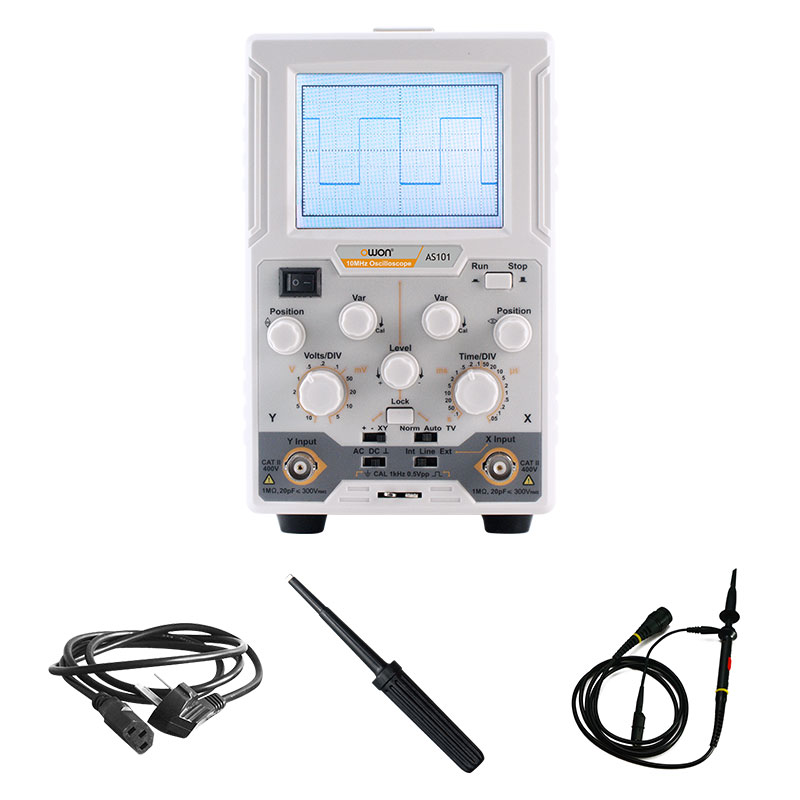
The oscilloscope is delivered excellently packaged in a sturdy and large cardboard box with lots of protective material around the device. Besides the oscilloscope itself, an IEC to Schuko power cable, a switchable oscilloscope probe and a clear and good English manual are included.
What immediately stands out is that the BNC connector of the probe is fully insulated. From such a small detail one can already conclude that a manufacturer pays a lot of attention to its products.
 |
| The scope of delivery of the package. (© 2021 Jos Verstraten) |
The AS201 oscilloscope
The device itself is housed in a sturdy metal case which, although it obviously does not contain a long cathode ray tube, still has the deep dimensions characteristic of an analogue oscilloscope. Also in the design OWON respects the analogue disguise. The front panel is rather small with its dimensions of 117 mm by 192 mm and the knobs are therefore close together. The housing is 288 mm long and weighs about 1.8 kg.
The oscilloscope rests on four rubber feet. Unfortunately, the two front ones are not foldable, as is the case with most real analogue devices.
 |
The three views of the AS201. (© 2021 Jos Verstraten) |
The waveform update rate of the AS201
As one of the main features of the AS201, the manufacturer praises the waveform capture rate of 130,000 wfms/s. This would make the image you see on the screen similar to the image you see on a real analog oscilloscope. The 'waveform update rate' is a not so well known, but very important feature of digital oscilloscopes. Of course you know the concept of 'sampling rate' with digital oscilloscopes. This indicates how often the device samples the input signal within a measurement cycle. These sampled signals have to be processed by the software and the electronics into an image on the screen. This takes a certain time that is much longer than the sampling time and in this 'dead time' a digital oscilloscope is as blind as a mole. In that time interval, short and/or irregular spikes on the input voltage may occur which are missed by the oscilloscope. An analogue oscilloscope does not suffer from this phenomenon.
The recording of this random and irregular events on the signal becomes a matter of statistical probability due to the dead time. Sometimes such a spike is observed, sometimes not. The more often an oscilloscope is able to refresh the image, the higher the probability that a single event is captured and can be viewed. This fact is expressed by the specification 'waveform update rate' and expressed in wfms/s.
The question that then needs to be answered is whether a waveform update rate of 130,000 wfms/s is something a manufacturer can be proud of. Most cheap devices do not even mention this specification. So we have to look at the more expensive models:
- UNI-T UTD2102CEX: 2,000 wfms/s, price € 299.00
- Owon XDS3062A: 75,000 wfms/s, price € 419.00
- Keysight DSOX1102A: 50,000 wfms/s, price € 775.00
The conclusion can definitely be that a waveform update rate of 130,000 wfms/s is exceptionally high and therefore indeed a feature worth mentioning.
The controls of the AS201
The AS201 has all the controls, shown in the figure below, that are familiar from an analogue oscilloscope plus one button that does not really belong on this device at all: Run/Stop.
- [1] The LCD screen
With dimensions of 74 mm x 55 mm, resolution of 320 x 240 pixels and 65,536 colours. - [2] Run/Stop
The only button that does not belong on an analogue device. It allows you to freeze the image on the screen. Useful for teaching and if you need to take a picture of the screen. - [3] Var
Fine adjustment of the time base speed, rightmost position is the calibrated position. - [4] Position
Adjustment of the horizontal position of the trace on the screen. - [5] Level
Setting of the signal level at which the oscilloscope triggers. - [6] Time/DIV
The speed of the time base, so the speed with which the 'light spot' moves from left to right over the screen. In twenty steps adjustable between 100 ms/div to 50 ns/div in the known 1/2/5 ratio. - [7] Lock
When you push this button the triggering is automatically set to the best signal level of the input signal. - [8] Norm/Auto/TV
Selects the preferred trigger mode. In 'Norm' mode, no trace is written on the display if no input signal is present. Writing of traces starts when an input signal that meets the trigger conditions is present. In 'Auto' mode, the unit writes one trace on the screen even if there is no input signal. The 'TV' mode triggers on old fashioned analog TV signals. - [9] X Input
Input for an external trigger signal or for the horizontal deflection in XY mode. - [10] Int/Line/Ext
Selects the desired trigger source: internal, external or the 50 Hz line voltage. - [11] CAL signal
A 0.5 V square wave signal with a frequency of 1 kHz is present at this pin. This is used to adjust the 1/10 attenuator in the oscilloscope probe. - [12] CAL ground
The ground reference of the 1 kHz signal. - [13] AC/DC/GND
Selects the vertical coupling mode. In 'AC' position only the AC voltage at the input is coupled through. In 'DC' position, any DC voltage present will also be displayed. In the 'GND' position, the input of the AS201 is internally grounded so that you can see where the ground reference is set on the screen. - [14] Y Input
The vertical input of the oscilloscope to which you connect the signal to be measured. Has an input resistance of 1 MΩ ±2 %, parallel to 20 pF ±5 pF. The maximum input voltage is ±400 V. - [15] +/-/XY
In position '+' the device triggers if the positive edge of the input signal exceeds the trigger level. In the position '-' the same happens on the negative edge. In the 'XY' position, the AS201 works in the XY mode, where you apply voltages to both the X and Y inputs, and the location of the spot on the screen is determined by both voltages. - [16] Volts/DIV
With this button you select the vertical sensitivity of the oscilloscope. Eleven positions from 10 V/div to 5 mV/div in the well-known 1/2/5 ratio. - [17] Position
Sets the vertical position of the trace on the screen. - [18] Var
Fine adjustment of the vertical sensitivity, most right position is the calibrated position. - [19] O/I
Power switch.
 |
| All the controls of the AS201. (© 2019 LILLIPUT Company) |
The other specifications of the AS201
In the previous paragraph, most of the specifications of the oscilloscope have been discussed under the relevant buttons. Specifications not yet discussed are:
- Bandwidth Y-channel mode AC: 10 Hz ~ 20 MHz (-3 dB)
- Sampling rate: 0.5 Sa/s ~ 100 MSa/s
- Waveform interpolation: sin(x)/x
- Time base accuracy: ±100 ppm
- Rise time: less than 30 ns
- Trigger range: ±4 divisions from centre of screen
- Impedance external trigger input: 1 MΩ ±2 %, 20 pF ±5 pF
- Maximum trigger voltage: 400 Vpeak to peak
- Bandwidth X channel: 10 Hz ~ 1 MHz (-3 dB)
- Sensitivity X-channel: 0,5 V/div
- Power supply voltage: 100 Vac ~ 240 Vac
- Power consumption: 15 W max.
Strangely enough, not a word is mentioned about a rather important property, the number of bits the ADC works with (resolution).
The electronics in the device
Removing the case
The case consists of a lower metal U-shaped frame in which the PCBs and the front plate are mounted and an upper metal U-shaped cover that is screwed to the lower frame with a number of bolts. After unscrewing these bolts, you can remove the cover and the internal electronics are revealed. This is a pleasant surprise, as everything that is visible indicates that the manufacturer has constructed the AS201 with great care.
On the back of the lower frame is a small power supply board, far away from the rest of the electronics. Unfortunately, this power supply is switched and not linear.
The oscilloscope's actual electronics are on three boards: one that is screwed to the bottom and two that are on the front panel and contain all the controls. The display is attached directly to the front panel, protected by a metal shield.
 |
| A view into the back of the AS201. (© 2021 Jos Verstraten) |
 |
| A view into the front of the AS201. (© 2021 Jos Verstraten) |
As the photo below shows, the interference sensitive parts of the device, the BNC connector and the input signal, are fully shielded on the PCB.
 |
| The shielding of the analogue input of the oscilloscope. (© 2021 Jos Verstraten) |
Testing the AS201
The first impression is excellent
The first impression after turning on the AS201 is excellent. The screen shows a 12 by 8 division grid and a horizontal trace after only a few seconds. It is strange that the manufacturer has chosen a blue color for the screen layout and the trace. After all, almost all analogue oscilloscopes have a green illuminated screen!
The oscilloscope is easy to operate and gives a very clear and stable image. The horizontal parts of the trace show hardly any quantisation artefacts.
However, the buttons are placed a little too close together for easy operation.
Both the calibration of the vertical sensitivity and the calibration of the horizontal deflection are excellent. At least, as far as this can be judged with an analogue scope, of course!

The analog bandwidth
We have tested several Chinese oscilloscopes and found that the bandwidth is often greatly exaggerated. The worst example was a device with a specified bandwidth of 100 MHz, which did not exceed 25 MHz (-3 dB frequency) when measured. So we are very curious what the specified bandwidth of 20 MHz of the AS201 represents in practice. To test this, we connect sine wave signals with identical amplitude but increasing frequency to the AS201. By comparing the size of the sine wave display on the screen you can get an idea of the bandwidth of the device.
In the figure below you can see that there is nothing to complain about. Even the sine wave with a frequency of 30 MHz appears on the screen almost unattenuated. At 20 MHz, even a little extra gain is measured compared to 1 MHz.
 |
| Measuring the bandwidth of the AS201. (© 2021 Jos Verstraten) |
The reproduction of square waves
With a bandwidth of 20 MHz, it should be possible to reproduce square waves signals up to 1 MHz undistorted. In the figure below we have collected the reproduction of three square wave signals. These signals come from a function generator's TTL output and are connected to the AS201 with a BNC-to-BNC cable and a 50 Ω terminator.
 |
| The display of square waves. (© 2021 Jos Verstraten) |
The triggering of the oscilloscope
Nothing but good things about the triggering. The device also triggers very well on difficult signal shapes, like the one on the picture below. Our 2 x 100 MHz Hantek oscilloscope has some problems with this in its 'AUTO SET' function, but the AS201 puts, after some turning of the 'Level' potentiometer, a completely stable picture on the screen.
 |
| Even on such difficult signals the AS201 triggers stable. (© 2021 Jos Verstraten) |
The rise time of the AS201
The rise time is specified as less than 30 ns. At the maximum speed of 50 ns/div, the leading edge of a sharp-edge pulse should take up no more than 0.6 divisions of the image. The image below shows the leading edge of such a pulse, left on an oscilloscope with a rise time of only 3.5 ns, right on the AS201. Comparing both pictures, you can see that the pulse itself has a rise time of about 12.5 ns and that the rise time of the AS201 is within the specifications.
 |
| Measuring the rise time by means of a sharp-edge pulse. (© 2021 Jos Verstraten) |
The display of small signals
Digital oscilloscopes, in their most sensitive mode, can be bothered by digital distortions in the image. Not so surprising, because on the PCB of such a device, sharp-edge pulses with frequencies of several hundred MHz are present. A small parasitic capacitance is then already sufficient to spray HF harmonics. A good shielding between analogue and digital signal processing is therefore absolutely necessary.
As a check, we have set the AS201 to its most sensitive setting of 5 mV/div and short-circuited the input (left image). The horizontal trace written then is completely flat and shows absolutely no HF contamination.
 |
| Measuring a very small signal, 3 mVrms. (© 2021 Jos Verstraten) |
The XY mode
 |
| The screen image in the XY mode of the AS201. (© 2021 Jos Verstraten) |
Our conclusions about the OWON AS201
The quality of the product
We can be brief about this: excellent! A lot of care has gone into the construction of the device. Its performance as a simple 'analogue' oscilloscope is also excellent.
Of course we miss some useful features that are standard in a digital oscilloscope and could have been integrated into the AS201's firmware without extra cost. However, these are missing from every analogue oscilloscope and it would be unfair to expect them from this product.
Is the AS201 a worthwhile investment?
We find this a difficult question to answer. We assume that the manufacturer has done marketing research and found that there is a demand for such a digital oscilloscope disguised as an analogue one. However, the AS201 costs at least € 139.95 and for much less than that you can buy a second-hand real analogue instrument with two channels and a much wider bandwidth on eBay or Marketplace. For a hundred euros more, you can buy a real digital oscilloscope with two channels, 100 MHz bandwidth and many additional functions directly from China.
On the other hand, a comparable product, Voltcraft's AO-610 analogue oscilloscope with a bandwidth of only 10 MHz, costs about € 185.00.
We fell a bit in love with the AS210, I guess it has to do with our age and youth sentiment. Although we usually sell tested products for a nice price to electronics hobbyists, we decided to keep the AS201 as a second oscilloscope in our lab.

OWON AS201 oscilloscope