
|
After resistors and polyester capacitors, electrolytic capacitors are the most frequently used parts in the daily practice of the hobby lab. Fortunately, you can also buy these parts very cheaply from Chinese webshops. We investigated the quality of such an offer. |
Introduction to the 25 x 25 = 625 electrolytic capacitors package
625 electrolytic capacitors for € 22.21
Via AliExpress and Banggood, twenty-five electrolytic capacitors of twenty-five different values/voltages are offered for a price of less than €25. That means an average price of four cents per capacitor! If you keep in mind that for the cheapest type in the package (1 μF ~ 50 V) you pay eight cents at Conrad and for the most expensive type (2,200 μF ~ 25 V) € 0.94, then it is clear that this is an incredibly cheap offer.
Firework or electrolytic capacitors?
Firework or electrolytic capacitors?
Chinese electrolytic capacitors are being criticised on various electronics forums and on YouTube. These parts are said to be completely unreliable, they can explode at any moment and are therefore better advertised as firework than as electronic parts. We bought one of these assortment from Banggood and extensively tested 90 out of the 625 units supplied. Of the 90 tested, only one was defective and had such a high leakage current that the component 'exploded' after ten seconds. There is a reason why the word 'explode' is within quotation marks, as all that happened was that the aluminium housing burst open at the place intended for that purpose, namely at the top of the component.
 |
| The one electrolytic capacitor that did not survive our test. (© 2021 Jos Verstraten) |
What is supplied
You can find the assortment at Banggood or AliExpress by searching 'Geekcreit 1uF-2200uF 625 pcs 25 values electrolytic capacitor'. This package contains the following electrolytic capacitors:
- 25 pieces of 1 μF ~ 50 V
- 25 pieces of 3.3 μF ~ 50 V
- 25 pieces of 4.7 μF ~ 50 V
- 25 pieces of 6.8 μF ~ 50 V
- 25 pieces of 10 μF ~ 25 V
- 25 pieces of 10 μF ~ 50 V
- 25 pieces of 33 μF ~ 50 V
- 25 pieces of 47 μF ~ 16 V
- 25 pieces of 47 μF ~ 25 V
- 25 pieces of 47 μF ~ 50 V
- 25 pieces of 100 μF ~ 16 V
- 25 pieces of 100 μF ~ 25 V
- 25 pieces of 100 μF ~ 50 V
- 25 pieces of 330 μF ~ 25 V
- 25 pieces of 330 μF ~ 50 V
- 25 pieces of 470 μF ~ 16 V
- 25 pieces of 470 μF ~ 25 V
- 25 pieces of 470 μF ~ 50 V
- 25 pieces of 220 μF ~ 16 V
- 25 pieces of 220 μF ~ 25 V
- 25 pieces of 220 μF ~ 50 V
- 25 pieces of 1,000 μF ~ 16 V
- 25 pieces of 1,000 μF ~ 25 V
- 25 pieces of 1,000 μF ~ 50 V
- 25 pieces of 2,200 μF ~ 25 V
The electrolytic capacitors are delivered in 25 plastic bags without further identification of the types. With this quantity and these types of electrolytic capacitors, you will be able to hobby for the next few years!
The appearance of the electrolytic capacitors
The appearance of the electrolytic capacitors
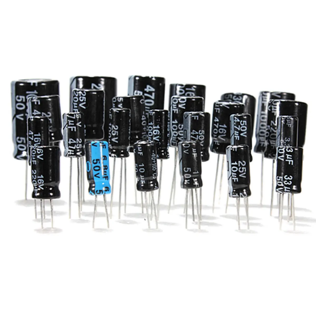
All supplied capacitors are radial versions. This means that they are upright cylinders where the connecting wires emerge from the bottom. The smallest type (1 μF ~ 50 V) has a diameter of 4 mm and a height of 8 mm. The largest type (2,200 μF ~ 25 V) has a diameter of 13 mm and a height of 20 mm.
The capacitors are enclosed in an aluminium casing. An electrolytic capacitor contains a semi-liquid substance that produces gases when heated. If the electrolytic capacitor gets too hot, these gases will exert such pressure on the casing that it could explode. To prevent this, two notches have been made in the top of this casing, which ensure that the electrolytic capacitor does not explode but only bursts open.
A black plastic cover is crimped over the aluminium shell, on which the data of the component are printed. The negative connecting wire is clearly indicated by a white bar. This lead is also clearly shorter than the positive lead. Incorrect connection of the capacitors is therefore almost impossible!
 |
| The appearance of the supplied electrolytic capacitors. (© Banggood) |
The manufacturers
Although all types look identical and it therefore seems as if they all come from the same manufacturer, this is not the case. We come across the following manufacturers:
How to accurately measure the capacitance of electrolytic capacitors
We performed the measurements with an ET4401 RLC meter from East Tester. Switched to the measuring function 'elco', this meter applies the signal shown below over the electrolytic capacitor. The position of the left yellow arrow indicates the zero level. You can see that the combination of 120 Hz signal and bias indeed ensures that the voltage across the electrolytic capacitor can never change polarity.
How and what we measured
The measurement results
Interpretation of the measurement data
When translating this table into the quality of the tested electrolytic capacitors, the question 'what is an acceptable leakage current of an electrolytic capacitor?' must be answered. A formula found via Google states that the leakage current of an electrolytic capacitor after one hour of formatting should be equal to:
What is the ESR of an electrolytic capacitor?
ESR absorbs power and causes heat-up
Two currents flow through an electrolytic capacitor in the smoothing circuit of a power supply. On the one hand, a charging current flows from the rectifier to the electrolytic capacitor and, on the other hand, a discharging current flows from the electrolytic capacitor to the connected electronic circuit. These two currents also flow through the ESR and this has two nasty consequences. A current flowing through a resistor generates a voltage across the resistor, according to the formula V = I ● R. It will be clear that the voltage generated across the ESR is not available to the circuit to be powered. The greater the ESR, the more voltage is lost. A current flowing through a resistor also generates power, according to the formula P = V ● I. This power causes the ESR and therefore the capacitor to heat up. This heating results in an increase in the leakage current of the electrolytic capacitor. The quality of the electrolytic capacitor will slowly but surely deteriorate and at a certain moment, the leakage current will be so high that the electrolytic capacitor will be defective.

Measuring the ESR
You cannot measure this important parameter of an electrolytic capacitor with a multimeter. Our RLC meter ET4401 does it fully automatically as a second measurement in the display when measuring the capacitance. So, in determining the capacitance and tolerance of the ninety selected electrolytic capacitors, we also noted down the ESR. In the table below you can see the measurement data again conveniently summarised with lowest measured value, average calculated value and highest measured value within a series of ten identical electrolytic capacitors.
Interpretation of the measurement data
The question is 'what is an acceptable value for the ESR of an electrolytic capacitor?'. The manufacturer of the ESR70, a device specially designed for measuring the ESR of electrolytic capacitors, provides in the manual of this device a table with typical ESR values of all kinds of values and voltages of electrolytic capacitors. If we use this table as a reference, it appears that these cheap electrolytic capacitors from China do an excellent job. The measured ESR values are lower than what is indicated as typical in the ESR70 manual.
Introduction
The measurement results
Because this measurement is rather time-consuming, we have only measured the influence of temperature on the properties of one electrolytic capacitor. The results are summarised in the table below.
Interpretation of measurement data
The electrolytic capacitors clearly have a positive temperature coefficient with regard to their capacitance. Over a temperature range of 70 °C, the capacitance increases by 123.5 μF. That corresponds to a tempco of 1.76 μF/°C. That the ESR decreases as the temperature rises is something that every electronic engineer can understand. The course of the leakage current is spectacular, which is also to be expected. Strangely enough, this parameter first decreases slightly and then increases very rapidly.
To put things in a clearer perspective, the measurement data are summarised in a graph in the figure below. The vertical axes are not calibrated, this graph is only meant to quickly see what the temperature does to the properties of these electrolytics.
Introduction
Electrolytic capacitors or time bombs? None of our tests show that these cheap components are extremely unreliable. Besides...these electrolytic capacitors are used everywhere in the world in perhaps billions of USB chargers and similar ridiculously cheap Chinese devices. If the critics were really right, there would have been a worldwide pandemic of exploding or burning chargers. There are no reports of such an event in the press. So the stories are probably exaggerated. In any case, we are very satisfied with this purchase and will use these capacitors in our designs without any fear.

(Banggood sponsor ad)
Geekcreit 1uF-2200uF 625 pcs Electrolytic Capacitor Kit
Although all types look identical and it therefore seems as if they all come from the same manufacturer, this is not the case. We come across the following manufacturers:
- PH-EMG
- Huahong
- United
- Fencon
- Nichicon
- Chanxing
High tolerances common to electrolytic capacitors
Measuring the capacitance and tolerance
High tolerances common to electrolytic capacitors
If you buy a resistor of 1 kΩ, you expect it to have this value. With electrolytic capacitors it is not that simple. Tolerances of ±20 % are quite normal for such components. This means that, in practice, an electrolytic capacitor printed as 100 μF may have a capacity of somewhere between 80 μF and 120 μF.

Digital multimeters are completely unreliable
Digital multimeters are completely unreliable
All modern digital multimeters offer the possibility of measuring capacitors. For non-electrolytic capacitors, this measurement can be quite accurate. However, for determining the capacitance of electrolytic capacitors, these meters are absolutely inadequate, no matter what the specifications of the meter claim. This has to do with the way digital multimeters determine the capacitance of a capacitor. This measurement method is shown in the figure below.
The electrolytic capacitor Cx to be measured is connected to an electronic change-over switch S1. In the drawn position 1 the capacitor is discharged via the resistor R1 with the discharge current Idischarge until it is completely discharged. A moment later, the meter switches S1 to position 2 and the capacitor is now charged with a very constant current Icharge, supplied by a very stable current source. This charging continues until the voltage across the capacitor has risen to a certain value Vref. At this point, the measuring circuit switches the electronic switch back to position 1. The time required to charge the capacitor from 0 V to the reference value Vref is directly proportional to the value of the capacitor. After all, from electricity theory you know:
Q = V • C
The charge in a capacitor is equal to the capacitance of the capacitor multiplied by the voltage across the component.
But also:
Q = I • t
The charge in a capacitor is equal to the current flowing in the capacitor, multiplied by the time this current flows.
Thus it is:
V • C = I • t
Or:
C = [I • t] / V = [I / V] • t = cte • t
For the circuit discussed, the charging current Icharge and the reference voltage Vref are constant. Therefore, there is indeed a proportional relationship between the value C of the capacitor and the charging time t which is necessary to charge the fully discharged capacitor to the reference voltage Vref. By measuring this time t, the processor in your multimeter can calculate the value of the capacitor and show it on the display.
 |
| The principle by which your multimeter measures capacitors. (© 2021 Jos Verstraten) |
This system works excellently and very accurately when measuring non-electrolytic capacitors. These have completely negligible leakage currents. Electrolytics do not have this and you can represent this large leakage current by a parasitic resistor Rleakage that is in parallel across the capacitor Cx (see diagram above). A current will flow through this resistor, the leakage current of the capacitor. Since the current source supplies a constant current, this leakage current is subtracted from the current flowing through the ideal capacitor Cx. The charging time of the capacitor is therefore influenced by the magnitude of the leakage current. If you measure two electrolytic capacitors with identical capacitances but different leakage currents, your digital multimeter will display two very different capacitance values.
The proof of this theory
The proof of this theory
We have checked this theory with our own digital multimeter VC650BT from Voltcraft. We measured a capacitor of 10 μF and one of 1,000 μF and displayed the voltages across these components on the screen of our oscilloscope. You can see in the oscillograms below how the voltage across the capacitors rises linearly from zero to the same reference voltage and then the capacitors are discharged again.
 |
| The voltages across the capacitors when measured with a digital multimeter. (© 2021 Jos Verstraten) |
How to accurately measure the capacitance of electrolytic capacitors
To measure electrolytic capacitors accurately, you must use a completely different measuring principle. That principle is called 'CV measurement' and it is not included in any multimeter, but it is in the RLC meters of the better kind. You can recognise such measuring devices by the four BNC connectors that are standard on them. In such meters, capacitors are measured by applying a 120 Hz sine wave voltage with a value of 1.0 V to the capacitor. This AC voltage is superimposed on a small bias DC voltage of 1.5 V, so that the capacitor remains well polarised. This combination of two voltages causes a measuring current of 150 Hz to flow through the electrolytic capacitor.
Such an RLC meter has four BNC connectors that have the following standard designations:
- Hcur: provides the measuring voltage for the electrolytic capacitor.
- Hpot: measures the voltage over the capacitor.
- Lcur: feeds the measuring current to the measuring circuit.
- Lpot: set the negative side of the electrolytic capacitor on virtual earth.
After all, the non-inverting input of the op-amp is at ground potential and the op-amp will try to put its inverting input at ground potential as well.
The RLC meter contains two electronic measuring circuits, symbolically represented in the schematic by M1 and M2. However, these are not ordinary voltmeters, but circuits which not only measure the magnitude, but also the phase of the voltages. The processor in the meter can derive a lot of properties of the capacitor from these two measurements, such as capacitance C, impedance X, ESR (read more), the phase shift Φ and the quality factor Q.
 |
| The principle of the CV measurement. (© 2021 Jos Verstraten) |
We performed the measurements with an ET4401 RLC meter from East Tester. Switched to the measuring function 'elco', this meter applies the signal shown below over the electrolytic capacitor. The position of the left yellow arrow indicates the zero level. You can see that the combination of 120 Hz signal and bias indeed ensures that the voltage across the electrolytic capacitor can never change polarity.
 |
| The signal over an electrolytic capacitor in a CV measurement. (© 2021 Jos Verstraten) |
How and what we measured
From the total assortment of 625 electrolytic capacitors, we selected nine values and measured ten of each value. In the table below you can see the average value of those ten measurements, the average percentage deviation and the minimum and maximum values we measured in the series. This way you get an insight in not only the average values, but also in the extreme values.
 |
| The results of our capacitance measurements summarised in one table. (© 2021 Jos Verstraten) |
Interpretation of the measurement data
What has not been taken into account in these measurements is the so-called 'formatting' of electrolytic capacitors. The dielectric insulation layer, the extremely thin layer that separates the two plates, is partly built up if the capacitor is or has been under voltage. The measurement results in the table above are measured on electrolytic capacitors as they were delivered by Banggood, so without extra formatting.
We can conclude from these results that these cheap capacitors can be approved with regard to their tolerance. The average tolerance for all measured types is even lower than the ±20 % which is considered normal for electrolytic capacitors. Of course there are large deviations, such as the one example of 220 μF that turned out to have a value of 403 μF. But as the table shows, that is really an exception.
Introduction
Measuring the leakage current
Introduction
As already mentioned, electrolytic capacitors are not absolute insulators for DC voltages. If you put a DC voltage across an electrolytic capacitor, a small current will flow through the component. This is called the 'leakage current' and it will be obvious that this current must be as small as possible. However, the problem is that this leakage current is not a constant. If you suddenly connect a new electrolytic capacitor to a voltage source, a large leakage current will flow through the capacitor. This current will first drop quickly and then slowly, which has to do with the formatting of the electrolytic capacitor. The decrease in leakage current is slower and slower, but even after ten minutes the process has not stabilised.
We illustrated this phenomenon for you by connecting a 1,000 μF electrolytic capacitor in series with a milli ammeter to a voltage of 25 V and logging the current through the component. You can see the results in the graph below.
 |
| The leakage current through a 1,000 μF electrolytic capacitor as a function of time. (© 2021 Jos Verstraten) |
The measurement results
The big question is when the leakage current through an electrolytic capacitor can be measured. Of course, it would take too much time to read the current through each specimen only after ten minutes. That is why we have adopted a standard time of twenty seconds. From the graph above, you can deduce that the real leakage current will therefore be smaller by a factor of two to three. A second question is at what voltage the leakage current is measured. It is not a good idea to use an electronic component to its maximum specified limits. This certainly applies to electrolytic capacitors. We have applied a voltage of 90 % of the maximum operating voltage specified on the capacitor. A capacitor with a maximum voltage of 50 V was thus measured at 45 V.
The results of our leakage current measurement of the same 90 items from the previous measurement are summarised in the table below. Again, we have not only noted the average leakage current, but also the individually measured minimum and maximum values.
 |
| The results of our leakage current measurements summarised in one table. (© 2021 Jos Verstraten) |
Interpretation of the measurement data
When translating this table into the quality of the tested electrolytic capacitors, the question 'what is an acceptable leakage current of an electrolytic capacitor?' must be answered. A formula found via Google states that the leakage current of an electrolytic capacitor after one hour of formatting should be equal to:
Ileakage = 0.002 • C • V
where Ileakage is expressed in μA if C is entered in μF and V in volt in this formula.
A 2,200 μF capacitor with an operating voltage of 25 V should therefore have a leakage current of:
Ileakage = 0.002 • 2,200 • 25 = 110 μA
According to this formula, the supplied capacitors would have too much leakage current. Nevertheless, we cannot imagine that the measured values would cause any problems. Even the worst electrolytic capacitor in this area, the one of 2,200 μF that draws a leakage current of 9.726 mA after twenty seconds at 22.5 V, dissipates a power of only 0.219 W. Of that, this capacitor will really not degenerate!
But it is of course true that a capacitor with such a large leakage current is not very useful as a DC-separator between two amplifier stages.
Measuring the ESR
What is the ESR of an electrolytic capacitor?
ESR is the acronym for 'Equivalent Series Resistance'. An electrolytic capacitor is defined by its capacitance, expressed in µF and by the maximum voltage you can put across the component, expressed in V. These two quantities are clearly indicated on the component. However, a parameter that is just as important but that you will never see on the component is the 'Equivalent Series Resistance'. As the name suggests, this is a resistor and one that is in series with the capacitance of the electrolytic capacitor. The ESR is a consequence of the way a capacitor is constructed. Especially electrolytic capacitors suffer a lot from this resistance. The normal value of the ESR depends on the capacitance and on the maximum voltage.
 |
| The ESR is a resistor that is internally in series with the ideal capacitor. (© 2021 Jos Verstraten) |
ESR absorbs power and causes heat-up
Two currents flow through an electrolytic capacitor in the smoothing circuit of a power supply. On the one hand, a charging current flows from the rectifier to the electrolytic capacitor and, on the other hand, a discharging current flows from the electrolytic capacitor to the connected electronic circuit. These two currents also flow through the ESR and this has two nasty consequences. A current flowing through a resistor generates a voltage across the resistor, according to the formula V = I ● R. It will be clear that the voltage generated across the ESR is not available to the circuit to be powered. The greater the ESR, the more voltage is lost. A current flowing through a resistor also generates power, according to the formula P = V ● I. This power causes the ESR and therefore the capacitor to heat up. This heating results in an increase in the leakage current of the electrolytic capacitor. The quality of the electrolytic capacitor will slowly but surely deteriorate and at a certain moment, the leakage current will be so high that the electrolytic capacitor will be defective.
Measuring the ESR
You cannot measure this important parameter of an electrolytic capacitor with a multimeter. Our RLC meter ET4401 does it fully automatically as a second measurement in the display when measuring the capacitance. So, in determining the capacitance and tolerance of the ninety selected electrolytic capacitors, we also noted down the ESR. In the table below you can see the measurement data again conveniently summarised with lowest measured value, average calculated value and highest measured value within a series of ten identical electrolytic capacitors.
 |
| The measured ESRs of the ninety selected electrolytic capacitors. (© 2021 Jos Verstraten) |
Interpretation of the measurement data
The question is 'what is an acceptable value for the ESR of an electrolytic capacitor?'. The manufacturer of the ESR70, a device specially designed for measuring the ESR of electrolytic capacitors, provides in the manual of this device a table with typical ESR values of all kinds of values and voltages of electrolytic capacitors. If we use this table as a reference, it appears that these cheap electrolytic capacitors from China do an excellent job. The measured ESR values are lower than what is indicated as typical in the ESR70 manual.
Measuring the influence of temperature
Introduction
Like all electronic components, the parameters of an electrolytic capacitor are influenced by temperature. To test this, we have constructed the following measurement setup. We own a rheostat, a wire-wound adjustable resistor. The resistor wire is wound on a hollow ceramic tube. Let the 1,000 μF ~ 25 V capacitors fit exactly in that hollow tube! We extended the connecting wires of one such component and pushed the part towards the middle of the tube (right on the photo below). On the other side (left on the photo), we pushed a thermocouple as far as possible into the tube. The resistor of the rheostat was connected to a lab power supply (yellow and blue test leads) and the voltage was regulated in such a way that the temperature in the internal of the ceramic tube slowly increased. In this way, the electrolytic capacitor is slowly heated up to the temperature measured with the thermocouple and the thermal influence on the various parameters can be measured.
 |
| The measurement setup for determining the influence of temperature on the specs of an electrolytic capacitor. (© 2021 Jos Verstraten) |
The measurement results
Because this measurement is rather time-consuming, we have only measured the influence of temperature on the properties of one electrolytic capacitor. The results are summarised in the table below.
 |
| The results of the temperature measurements summarised. (© 2021 Jos Verstraten) |
Interpretation of measurement data
The electrolytic capacitors clearly have a positive temperature coefficient with regard to their capacitance. Over a temperature range of 70 °C, the capacitance increases by 123.5 μF. That corresponds to a tempco of 1.76 μF/°C. That the ESR decreases as the temperature rises is something that every electronic engineer can understand. The course of the leakage current is spectacular, which is also to be expected. Strangely enough, this parameter first decreases slightly and then increases very rapidly.
To put things in a clearer perspective, the measurement data are summarised in a graph in the figure below. The vertical axes are not calibrated, this graph is only meant to quickly see what the temperature does to the properties of these electrolytics.
 |
| The results of the temperature measurements collected in one clear graph. (© 2021 Jos Verstraten) |
An endurance test attempt
Introduction
As stated in the introduction to this article, there are quite a few sources on the Internet that completely reject these capacitors. However, the tests we carried out give no reason to support this opinion. Of course, every electronic component only proves itself in the long run in a practical application. We have tried to simulate such a practical situation by carrying out a kind of endurance test. We arranged ten 2,200 μF ~ 25 V electrolytic capacitors in parallel and connected them to either a 24 V DC voltage or an 8 Ω resistor via the change-over contact of a relay. The coil of the relay is powered by a square wave voltage with a frequency of approximately 0.27 Hz.
 |
| The setup of our endurance test. (© 2021 Jos Verstraten) |
The practice
In one situation, the electrolytic capacitors are charged very quickly from the power supply, which has a current capacity of 5.0 A. In the other situation, the electrolytic capacitors are discharged somewhat less quickly, with a peak current of 3.0 A. The voltage across the electrolytic capacitors is shown in the oscillogram below. We performed this test for ten hours without interruption. That means that approximately 10,000 charge and discharge cycles were performed. All capacitors survived this test and appeared to be in good health at the end of this experiment, as it turned out after measuring their capacitance, ESR and leakage current.
In one situation, the electrolytic capacitors are charged very quickly from the power supply, which has a current capacity of 5.0 A. In the other situation, the electrolytic capacitors are discharged somewhat less quickly, with a peak current of 3.0 A. The voltage across the electrolytic capacitors is shown in the oscillogram below. We performed this test for ten hours without interruption. That means that approximately 10,000 charge and discharge cycles were performed. All capacitors survived this test and appeared to be in good health at the end of this experiment, as it turned out after measuring their capacitance, ESR and leakage current.
 |
| The voltage across the capacitors for one cycle. (© 2021 Jos Verstraten) |
Our opinion on these Chinese electrolytic capacitors
Electrolytic capacitors or time bombs? None of our tests show that these cheap components are extremely unreliable. Besides...these electrolytic capacitors are used everywhere in the world in perhaps billions of USB chargers and similar ridiculously cheap Chinese devices. If the critics were really right, there would have been a worldwide pandemic of exploding or burning chargers. There are no reports of such an event in the press. So the stories are probably exaggerated. In any case, we are very satisfied with this purchase and will use these capacitors in our designs without any fear.
Geekcreit 1uF-2200uF 625 pcs Electrolytic Capacitor Kit