Introduction to the O1 from BSIDE
The appearance of the device
The O1 is a rather large and rather heavy meter measuring 187 mm by 74 mm by 40.5 mm and weighing 252 g. The device comes in a brightly coloured close-fitting silicone jacket, with the result that you can buy the O1 in various colours: red, green or black. Although the meter is not ergonomically designed, thanks to this rough silicone jacket, it lies well in the hand. What is missing is a fold-out support, so you either have to hold the meter in your left hand or lay it flat on the table during measurements. Such a handy support would not be possible either, as the three 4 mm banana plug sockets are at the bottom of the meter. These are designed so that you can also use fully insulated 4 mm banana plugs.
An 'antenna' that allows you to detect the presence of mains voltage protrudes from the top of the housing and contains a bright white LED.
This meter has a large easy-to-read display measuring 57 mm by 43 mm, the brightness of which you can adjust. There are only ten control buttons whose function you will quickly master.
The oscilloscope/multimeter is powered by a 2,000 mAh Li-ion battery that you can charge via a USB-C connector hidden behind a lid on the back of the device.
 |
| The appearance of the BSIDE O1 meter. (© Banggood) |
Manufacturer, suppliers, prices
This oscilloscope/multimeter is supplied under the brand name BSIDE. Behind this name is the Chinese manufacturer 'Shenzhen Aimometer Co. Ltd'. This company mainly manufactures multimeters, oscilloscope/multimeters and current clamps and markets them under the brand names BSIDE and AIMOMETER. The device is offered through all known internet channels at prices ranging from € 50.00 to € 79.99. At the time of writing, the O1 was offered at Banggood for just € 48.84 and via AliExpress for € 63.92.
The O1 viewed from all sides
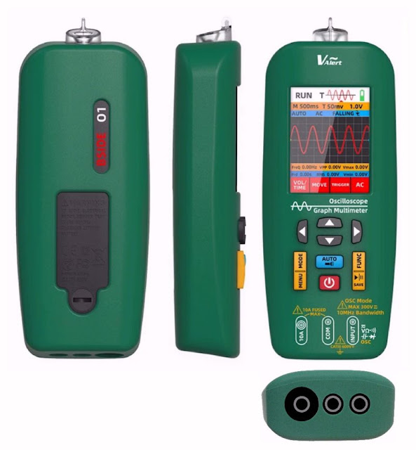
In the photomontage below, we have combined the main views of this oscilloscope/multimeter. Funny thing is that the hole in the housing behind which the measuring input '10A' is hidden is considerably larger than the holes for the other two inputs. This is not a bad thing psychologically! It immediately alerts you to the fact that you should use this input with care. After all, the resistance between this input and the 'COM' is minimal and you can cause tremendous short circuits if you do not use this input properly.
 |
| The different views of this oscilloscope/multimeter. (© 2024 Jos Verstraten) |
The back of the housing
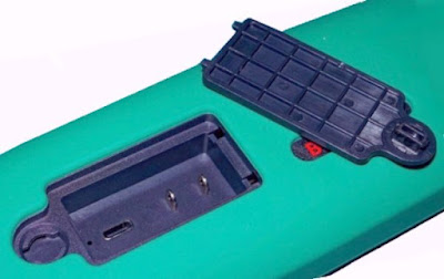
On the back, there is a cutout in the silicone jacket under which there is a lid. This can be opened with a coin. Under this lid is the USB-C connector that lets you charge the battery and connect the O1 to your PC. Between two bulky solder tabs is a square wave voltage with a frequency of 1 kHz and an amplitude of 3.5 V.
 |
| The lid to be opened on the back of the meter. (© 2024 Jos Verstraten) |
The scope of delivery
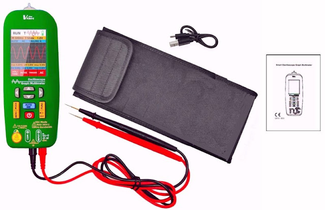
The meter comes in a sturdy large carrying case measuring 24 cm by 12.5 cm by 4.8 cm in which you can also easily store the two measurement leads. These test leads are very flexible and have a length of 100 cm. The banana plugs are fully shielded, the handles of the measuring tips are fitted with a safety ring that prevents your fingers from slipping and accidentally touching the metal tip. The tips are very sharp and have a length of 23 mm.
A very short (25 cm) USB-C to USB-A lead is included for charging the battery. The small printed manual is in Chinese and English and consists of 12 pages.
 |
| The scope of delivery of the BSIDE O1. (© 2024 Jos Verstraten) |
The manual
We have scanned it and put the English part on our account on the 'Internet Archive':
What we like about the BSIDE O1
- You can switch briefly to the oscilloscope function while measuring a voltage at the touch of a button to see what the measured voltage looks like.
- The display is large, 57 mm by 43 mm, and very clear.
- Both the multimeter and oscilloscope screens are nicely designed and contain easy-to-interpret data.
- You can save the display to the internal memory with a single keystroke.
- The internal memory can be read out on your PC as an external hard disk via a USB-C to USB-A data cable. You can thus export the saved screen dumps to your PC's hard drive.
- These screen dump files have a resolution of 240 x 320 pixels and a size of 150 kB.
What we like less about the BSIDE O1
- The oscilloscope has no BNC input so you cannot use a standard oscilloscope measuring probe.
- You cannot put the meter in a convenient reading position on your table.
- One decision by the manufacturer that we do not understand is the choice of the colour red for displaying the oscillograms. The screen background is black, so contrast is minimal. Why not the standard colours of yellow or light blue?
- The USB-C connector for charging the battery is in a very awkward place behind a lid on the back of the device.
- You cannot use the meter while charging the battery. At that point, the text 'USB MODE. Press UP to EXIT' appears on the screen, but the meter does not respond to pressing the '▲'-button.
- The supplied USB cable apparently only contains the ground and power but does not link the data lines. So to read out the memory to your PC, you have to use an additional USB-C to USB-A data cable.
- The O1 has a minimum current range of 5.999 A, which is obviously quite on the high side.
- To replace the fuse, you need to remove the silicone cover (which is not very easy) and then unscrew the meter.
- The oscilloscope's 'AUTO'-function sometimes takes a very long time (eight seconds!) to select the best values of sensitivity and time base.
The general specifications
- Display: 2.8 inch, IPS matrix
- Battery: Li-ion 2,000 mAh
- Measurement method: automatic
- Interface: Chinese or English
- Fuse: 250 V / 10 A, 5 mm x 20 mm
- Output: square wave 3.5 V / 1 kHz
- Automatic shutdown: 10 min ~ 30 min ~ 60 min ~ ∞
- Dimension: 187 mm x 74 mm x 40, 5 mm
- Weight: 252 g
Specifications of the oscilloscope
- Number of channels: 1
- Bandwidth: 10 MHz
- Rise time: less than 10 ns
- Sampling frequency: 1.5 Sa/s ~ 48 MSa/s
- Sample memory: 65 kB
- Input impedance: 1 MΩ, 16 pF
- Sensitivity: 20 mV/div ~ 10 V/div in 11 steps
- Accuracy: ± 3 %
- Signal coupling: DC ~ AC
- Compensation attenuation probes: 1/10
- Maximum input voltage: ±300 V
- Numeric measurements: period, frequency, peak-to-peak, maximum, minimum, RMS
- Time base: 100 ns/div ~ 20 s/div in 26 steps
- Time base accuracy: 20 ppm
- Trigger mode: automatic, normal, single
- Trigger start: falling or rising edge
- Auto mode: yes
The specifications of the multimeter
- Number of counts: 5999 or 9999
- Sampling rate: 3 measurements per second
- Range selection: automatic
- Measuring ranges DC voltage: 59.99 mV ~ 599.9 mV ~ 5.999 V ~ 59.99 V ~ 599.9 V
- Accuracy DC voltage: ±[0.8 % + 3] to ±[1.0 % + 3]
- Input resistance DC voltage: 10 MΩ
- Measuring ranges AC voltage: 59.99 mV ~ 599.9 mV ~ 5.999 V ~ 59.99 V ~ 599.9 V
- Accuracy AC voltage: ±[1.0 % + 3] to ±[1.2 % + 3]
- Input resistance AC voltage: 10 MΩ
- Frequency range AC voltage: 40 Hz ~ 1 kHz
- Measuring range DC current: 5.999 A ~ 10.00 A
- Accuracy DC current: ±[1.2 % + 3]
- Measuring ranges AC current: 5.999 A ~ 10.00 A
- Accuracy AC current: ±[1.2 % + 3]
- Measuring ranges resistance: 599.9 Ω ~ 5.999 kΩ ~ 59.99 kΩ
- Measuring ranges resistance: 599,9 kΩ ~ 5,999 MΩ ~ 59,99 MΩ
- Accuracy resistors: ±[1.0 % + 5] to ±[1.5 % + 5]
- Capacitor measuring ranges: 99.99 nF ~ 999.9 nF ~ 9.999 µF ~ 99.99 µF
- Capacitor measuring ranges: 999.9 µF~ 9.999 mF ~ 99.99 mF
- Accuracy capacitors: ±[4.5 % + 5] to ±[5.0 % + 20]
- Diode voltage measuring range: 3,000 V
- Conductance measuring range: 50,00 Ω
Lifetime of one battery charge
With a fully charged battery and with the screen intensity set to 50%, the oscilloscope lasts about 115 minutes.
The electronics in the BSIDE O1
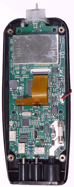
You can open the device by first removing the silicone cover and then unscrewing four bolts on the back of the housing. The battery is attached in the back half of the housing, the electronics in the front half. The battery is connected to the PCB with a small cable. In the picture below, you can see all the beauties the O1's PCB contains.
 |
| The PCB of the BSIDE O1. (© 2024 Jos Verstraten) |
The underside of the PCB shows the components of the multimeter. The '10A' current input (right) goes directly with a wide PCB trace to the sand-filled 10 A fuse, which has the standard dimensions of 5 mm by 20 mm. From that fuse, an equally wide trace goes to the current sensor resistor R010.
Above the 'VIN' banana plug socket, you can see the three large resistors of the input attenuator and the necessary protection circuitry. The green component is undoubtedly a PTC or a MOV. Here are also three relays responsible for switching the measurement ranges.
The code on most of the chips has been made unreadable. Under the ribbon cable connecting the PCB to the display is a AT32F403A from Artery. That is a microcontroller driven by a 32 bit ARM M4 core from Cortex.
Beneath the metal shielding is a host of other electronics, including an MS9280-type ADC. That chip can operate at 10 bit and at up to 35 MSa/s.
Working with the BSIDE O1
The control panel
The panel contains only ten push buttons, represented in the figure below.
- Red button:
Turns the device on and off. - AUTO:
After a short press, the oscilloscope searches for the best settings of sensitivity and time base. A longer press switches the white LED in the 'antenna' on or off. - MODE:
Switches from multimeter to oscilloscope and vice versa. - FUNC:
In multimeter mode, selects the quantity to be measured. In oscilloscope mode, allows you to set the four main functions. - SAVE:
A short press on this key 'freezes' the image. A longer press on this key creates a screen dump of the screen and saves it to the internal memory. - Cursor keys:
Depending on the selected function, these move the image or trigger level or select the sensitivity and time base. - MENU:
In oscilloscope mode, this key gives you access to twelve menu functions. In multimeter mode, pressing this key resets the 'MAX', 'MIN' and 'AVG' values on the display to zero.
 |
| The operation of the BSIDE O1. (© 2024 Jos Verstraten) |
Menu functions
As already written, the 'MENU' key works only in oscilloscope mode. You can select one of the 12 functions with the '◄' and '►' keys and adjust the selected function with the '▼' and '▲' keys.
- MODE:
Determines the trigger mode, adjustable to 'auto', 'single' and 'normal'. - EDGE:
Obviously selects the edge on which to trigger, namely 'up' and 'down'. - RATIO:
Takes into account the attenuation of the measurement probe you may be using, x1 or x10. - LIGHT:
Sets the intensity of the display to 30, 50, 80 or 100 %. - POWER:
Here you can set a 'low power mode' where the device consumes less power in idle mode. - RESTORE:
All settings are restored to factory values and the memory is cleared. - EXPORT:
Press the '▼' key to view the contents of the memory on your PC. By the way, our sample automatically goes to this function when a USB data cable is connected. - AUTOOFF:
Selects the time of automatic shutdown to 10 min ~ 30 min ~ 60 min ~ ∞. - CALIBR:
Calibrates the zero line of the oscilloscope, with no signal connected, back to the centre of the screen. - LANGUE:
Selects the interface language English or Chinese. - OUTPUT:
Selects the shape of the output signal on the two solder tabs. In our sample, this is set to 'square', the only option in this version of the firmware. According to the manufacturer, it is intended that future versions will also allow you to select sine, triangle and sawtooth here. - VERSION:
Shows the version of the software, in our model V1.0.3.
Using the BSIDE O1 as a multimeter
Starting up the device
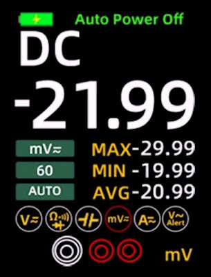
The BSIDE O1 always starts up in the 'measuring DC voltages' function with the range '5.999 V'. The screen dump below shows what the screen has to say. The big white data is obviously the measurement result. In the three green boxes, you can see the measurement magnitude, the range and the fact that this range was chosen automatically. Couldn't be otherwise, as a manual setting of the range is not possible with our specimen. The three yellow indications 'MAX', 'MIN' and 'AVG' show the maximum, minimum and average measurement value over the total measurement cycle. As already written, you can reset these values by briefly pressing the 'MENU' key.
One of the six circles will turn red. This indicates which quantity you are measuring. So in the figure below, mV DC voltage is being measured. Finally, the bottom edge of the screen shows which of the three banana plug sockets you should use to measure the selected quantity.
 |
| The screen when measuring DC voltage. (© Banggood) |
Selecting the magnitude of measurement
By pressing the 'FUNC' key or using the '◄' and '►' keys, you can set the measurement magnitude to:
- Voltage from range 5.999 V
- Resistance, diode and conductance, selectable using the '▼' and '▲' keys
- Capacitors
- Voltage up to 599.9 mV
- Current up to 5.999 A
- Voltage sensing
Switching between DC and AC voltage and current
You switch between DC and AC by pressing the '▼' and '▲' keys.
Detecting AC voltages
As with almost all meters we have tested, we are not particularly impressed with the O1's usability this function. You can't use it to detect conductors in walls and you have to roughly push the 'antenna' into a wall socket before anything changes on the display. But touching the screen of our laptop with the antenna sets the highest alarm!
The symbol on the right, representation of the antenna, turns green, yellow or red depending on the strength of the electromagnetic field being measured.
 |
| The screen when detecting AC voltages. (© 2024 Jos Verstraten) |
Using the BSIDE O1 as an oscilloscope
Starting up the oscilloscope
You switch from the multimeter to the oscilloscope function by briefly pressing the 'MODE' key. Connect the signal to be measured to the 'COM' and 'INPUT' banana plug sockets. Briefly press the 'AUTO' key. The software now determines the best sensitivity and time base settings, but this can sometimes take up to eight seconds, especially for small input signals!
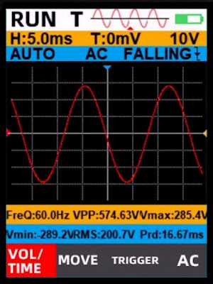
The screen dump below shows the display in this mode. What is immediately noticeable is that the red colour of the oscillogram does not contrast very well with the black background. Why not use the standard colours yellow or light blue here?
The top white frame shows 'RUN T' if the electronics are active and 'STOP T' if you have pressed the 'SAVE' button to freeze the image. 'WAIT T' appears when the software is busy finding the best settings of sensitivity and time base. The red oscillogram next to this text shows with an arrow which data from the sample memory is shown on the display.
The yellow frame shows the time base setting (H), trigger level setting (T) and sensitivity setting neatly side by side. The light blue frame displays the trigger mode setting, AC or DC coupling and trigger start.
Below the oscillogram, the yellow and light blue frames present six numerical data of the input signal: the frequency 'Fre', the peak-to-peak value 'VPP', the maximum value 'Vmax', the minimum value 'Vmin', the rms value 'VRMS' and the period 'Prd'. On most oscilloscopes, you can disable that numeric data if you wish. This is not possible with the O1.
The bottom black frame shows the four functions of the oscilloscope that you can select using the 'FUNC' key. The function you can currently set is shown in red.
 |
| The screen of the oscilloscope. (© Banggood) |
The four functions of the oscilloscope
You can select these by pressing the 'FUNC' key.
- VOL/TIME:
Setting the sensitivity and time base. You set the sensitivity with the '▼' and '▲' keys, the time base with the '◄' and '►' keys. - MOVE:
With the '▼' and '▲' keys, move the zero line of the oscillogram up or down. The '◄' and '►' keys scroll through all samples stored in memory. - TRIGGER:
The '▼' and '▲' keys move the trigger level up or down. You can see this by the yellow arrow, to the right of the oscillogram. - DC/AC:
The '▼' and '▲' keys select direct or alternating voltage coupling of the input signal to the oscilloscope.
Saving an oscillogram
Press the 'SAVE' button for more than one second. The current display is stored in memory as .BMP file with a resolution of 240 x 320 pixels and a size of 150 kB. You can, in the manner already described, with a USB-C to USB-A data cable, present the memory as an external hard disk to your PC and via Windows' 'Explorer' view, copy and delete these files. The files are in the 'PHOTO' folder.
Testing the oscilloscope in the BSIDE O1
The test signal on the back of the O1
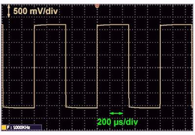
Although the practical use is rather limited, we did check on our oscilloscope the shape of the pulse you can take from under the lid on the back. It is indeed a nice rectangular-shaped pulse with a frequency of 1 kHz and an amplitude of about 3.5 V.
 |
| The test voltage supplied by the BSIDE O1. (© 2024 Jos Verstraten) |
Note
In the following images we have inverted the colours of the screen dumps of the BSIDE O1 to to increase the readability.
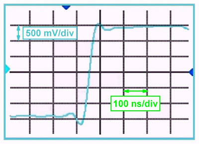
The rise time is specified by BSIDE as less than 10 ns. We are used to Chinese manufacturers always specifying this quantity much better than the actual value. This can be done with relative impunity, because most users of their equipment are unable to measure this rise time. We can, so we are curious.
We use a PCB called the 'Fast Edge Pulse Generator' for this purpose, which delivers a rectangular signal of 1.000 MHz with rise and fall times guaranteed to be less than 180 ps. That value is negligible compared to the BSIDE O1's rise time. You can therefore conclude that the rise time you see on the screen is caused by the electronics in the device. To minimise the influence of wiring, we connect this PCB to the 'COM' and 'INPUT' of the device with as short loose wires as possible.
The oscillogram below shows the result of our measurement. Because the fastest time base rate is only 100 ns/div, it is very difficult to read the true value of the rise time from the screen. But at least it is clear that the specified 10 ns is definitely not met!
 |
| Measuring the rise time of the O1. (© 2024 Jos Verstraten) |
Measuring bandwidth
Bandwidth is another specification that is exaggerated immensely by most Chinese manufacturers. So we are very curious to see what the BSIDE O1, with its specified bandwidth of 10 MHz, gets out of it.
The best method to check the bandwidth of an oscilloscope is to use a very wideband sine generator. Of course, the prerequisite is that this device is guaranteed to have an absolutely straight amplitude/frequency characteristic. This means that if you set an output voltage of 1.0 V, the device delivers an output voltage of 1.0 V at all frequencies. Our function generator DG1022 from Rigol meets this requirement.
Such a measurement goes as follows. You first input a sine wave signal with a frequency of 1 kHz and note where the peaks of the sine wave are on the screen. This is the peak-to-peak value of the signal. You slowly increase the frequency, obviously leaving the sensitivity of the oscilloscope in the same position. You see the signal on the screen getting smaller and smaller. Somewhere there is a frequency where the peak-to-peak value of the sine wave becomes equal to 70 % of the peak-to-peak value of the signal at 1 kHz. The attenuation is then equal to 3 dB and that is the definition of bandwidth.
We performed this measurement on the O1 and used frequencies of 1 kHz, 5 MHz, 8 MHz and 10 MHz. The results are summarised in the figure below. We have represented the peak-to-peak value at 1 kHz with two red lines. It clearly shows that the frequency response of the device is absolutely straight up to 5 MHz. At 8 MHz, the signal is already slightly attenuated, but is still nicely reproduced within the -3 dB norm. At 10 MHz, the rather low sample rate starts to play a role and the sine wave is no longer faithfully displayed.
We can therefore say that the real bandwidth of the BSIDE O1 is at least 8 MHz. An impressive value for such a cheap little device!
 |
| Measurement of the bandwidth of the BSIDE O1. (© 2024 Jos Verstraten) |
Representation of a perfect 1 MHz square wave
The PCB 'Fast Edge Pulse Generator' produces a perfect square wave with a frequency of exactly 1.000 MHz. In the figure below, you can see on the right how the BSIDE O1 displays this signal. For comparison, you can see on the left how our oscilloscope XDS2102A from OWON reproduces the same signal.
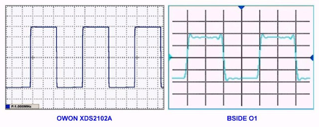 |
| Display of a perfect 1 MHz square wave. (© 2024 Jos Verstraten) |
Display of a perfect 5 MHz sine wave
In the picture below of the O1's screen, you can see how this device reproduces a perfect 5 MHz sine wave from our Rigol function generator DG1922. There is nothing wrong with that!
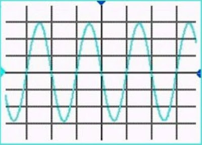 |
| Display of a perfect 5 MHz sine wave voltage. (© 2024 Jos Verstraten) |
Testing the multimeter in the BSIDE O1
Accuracy at DC voltage
We use various DC voltage sources and resistance dividers to cover a range from 10 mV to 500 V. We consider the measurements of our Fluke 8842A as 100 % reference and calculate the percentage deviation of the BSIDE O1's measurements from this reference. Neatly, the specimen tested remains well below the specified deviation of ±0.8 % to ±1.0 % in almost all measurements. The automatic measurement range selection works quickly and accurately.
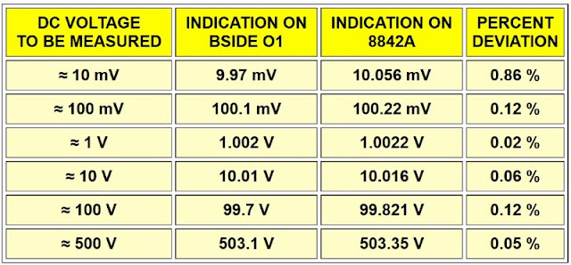 |
| Accuracy in measuring DC voltages. (© 2024 Jos Verstraten) |
Measuring DC currents
We connect the BSIDE O1 in series with our ET3255 multimeter on a power supply switched as current source. The table below compares the measurement results. It's not too bad! Despite the anything but sensitive measuring range of 5.999 A, you can still measure currents in the mA range quite accurately, although obviously with a small resolution.
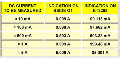 |
| Accuracy in measuring DC currents. (© 2024 Jos Verstraten) |
Measuring resistors
For this test, we have at our disposal a set of reference resistors with a tolerance of ±0.01 % plus some less accurate ones. As a reference meter, we obviously use our 8842A from Fluke. This meter uses a four-wire kelvin probe, which is not possible with the BSIDE O1. The results are again summarised in a table.
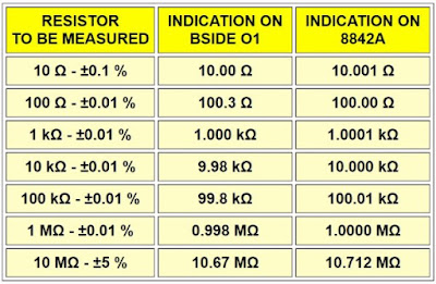 |
| Accuracy in measuring resistors. (© 2024 Jos Verstraten) |
Measuring capacitors
Thanks to a set of five accurate capacitors with a tolerance of ±1 % and three reference capacitors with a tolerance of only ±0.05 %, we can test the performance of the BSIDE O1 when testing such components. Above 1 µF, we measure ordinary electrolytic capacitors from our stock. As a reference meter, we use East Tester's ET4401 with an accuracy of ±0.2 % for non-electrolytic capacitors.
As could be expected, the O1 measures at small values with a fairly large error. A 100 pF capacitor is even given more than double the value! This is a feature of almost all measuring instruments that measure capacitors with only two wires instead of a four-wire probe, as professional RLC meters do.
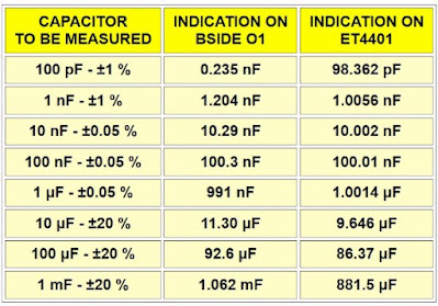 |
| Accuracy in measuring capacitors. (© 2024 Jos Verstraten) |
Measuring 50 Hz alternating voltages
In most cases, you use the AC voltage function of a multimeter to measure 50 Hz voltages. Hence, we tested this with a function generator for small voltages and with a variac for the larger ones. Our ET3255 from EastTester is again used as a reference meter. Again, it shows that you can trust the measurements with the O1.
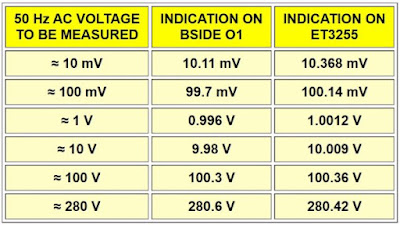 |
| Accuracy in measuring 50 Hz AC voltages. (© 2024 Jos Verstraten) |
The frequency range in AC voltage measurements
This is specified up to 1 kHz. We verify this by providing a voltage of 1 Vrms and varying frequency to the BSIDE O1. The ET3255 is again used as a reference meter. The result is summarised in the table below. The specified bandwidth of 1 kHz is a bit exaggerated, as you will already be measuring with an error of almost 8 %.
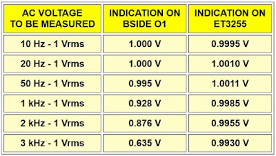 |
| The frequency range when measuring AC voltages. (© 2024 Jos Verstraten) |
Our opinion on the O1 from BSIDE
The electronics hobbyist gets for barely € 50.00 a very useful and reliable measuring instrument for measurements in almost all circuits he or she encounters. Admittedly, the oscilloscope has only the basic functions, but this is good enough for most measurements in the hobby range. What stands out is the measured bandwidth of 8 MHz and the excellent way a sine wave at that frequency still appears on the screen.
The main criticism we have of this meter is the very poor contrast on the oscilloscope's screen. By choosing a lighter colour (yellow or light blue) in the software to display the oscillograms, this drawback can be overcome. A second inconvenience is that the 'AUTO' function sometimes takes a very long time to select the correct settings of sensitivity and time base. If you want to measure several signals in quick succession, this is rather frustrating.
A pity is the fact that the manufacturer did not opt for a BNC input for the oscilloscope. That would obviously increase the price somewhat, but would allow the use of a standard oscilloscope measuring probe.


