|
The Chinese company ICStation brings nice DIY kits to the market, we have already reviewed several of them. Now we test a clock with the modern filament LEDs as segments of the seven-segment displays. |
Introduction to the HE056 kit
The end result
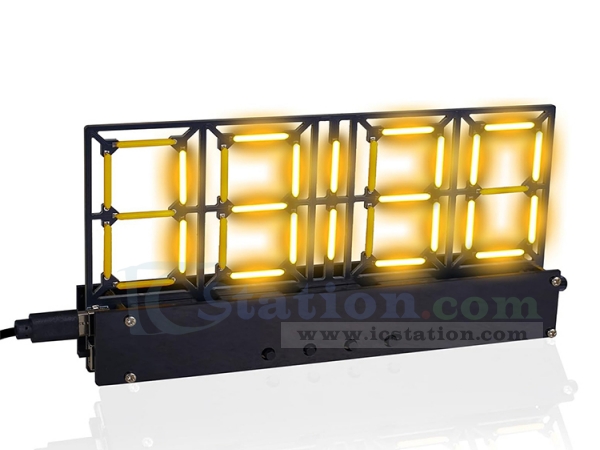
The picture below shows the end result of a few hours of tinkering. A four-digit clock with digits measuring 48 by 25 mm. These dimensions are due to the use of 18 mm long so-called filament LEDs that make up the display's segments. The clock is housed on a PCB measuring 82 mm by 155 mm and is powered from 5 Vdc. The circuit consumes about 500 mA at maximum intensity of the displays. On those four digits, after selection by pressing a button, the time, date, day of the week, year and alarm time appear. Between the four displays are two additional filament LEDs that flash to the rhythm of the seconds.
A real-time clock-chip is present, kept energised by a 3 V button cell. So you only have to set the correct date and time once, and the chip remembers this data and keeps the clock running evenly.
A potentiometer lets you set the intensity of the display from softly glowing to very bright.
 |
| The end result of this building kit. (© 2025 Jos Verstraten) |
Supplier and prices
This kit is offered by ICStation for $ 13.79. The disadvantage of ICStation is that you cannot pay with iDEAL. Via AliExpress, where you can, you buy the building kit including shipping for € 18.81.

Filament LEDs
Filament LEDs
Filament LED lamps have been around since 2013. At that time, the first versions of these fake incandescent lamps appeared on the market. They have since become increasingly popular, especially thanks to their retro look, which is popular in interior design. The active elements in these lamps are the filament LEDs and, of course, these are also sold separately. A filament LED contains several small LED chips that usually emit blue light and are mounted on a long, thin, transparent rod. This rod, the filament, is made of glass or ceramic, as these materials transmit light well. The filament is coated with a phosphor layer. This material converts the blue light from the LED chips into warm white or yellow light. This is called luminescence, a technique also used in ordinary LEDs. Depending on the composition of this coating, the light can be made 'warmer' (yellowish) or 'cooler' (white or bluish).
Within each filament rod, the LED chips are connected in series. Multiple filaments are then connected in parallel or in series-parallel to achieve the desired light output of the lamp.
 |
| Imitation incandescent lamp from Philips with the loose filament LEDs on the right. (© 2025 Jos Verstraten) |
The parts supplied
The picture below shows the parts supplied. Below the PCB are two black perspex panels that form a small enclosure around the bottom of the PCB, where the electronics are located. Six DIL IC sockets are supplied for the total of six ICs that make up the electronics. A USB-C connector is used to connect the circuit to a 5 Vdc power supply. A USB-A to USB-C cable is included. The clock is powered by an included CR2032 button cell. Our building kit included 33 filament LEDs, while only 30 are needed.
 |
| The supplied parts. (© 2025 Jos Verstraten) |
The manual
The manual consists of one sheet of A4, where eighteen small photos explain each step of the assembly.
The PCB for the filament clock
In the photo below, we have enlarged the artfully designed PCB so that the position of the various components with their reference designators is very clear. If you assemble the PCB, you will no longer see these reference designators, hence this image. Thanks to the various cut-outs in the PCB, the thirty filament LEDs are hanging free in the air. That gives this clock its unique look!
 |
| The PCB for the circuit. (© 2025 Jos Verstraten) |
The electronics in the clock
Unfortunately, no information can be found about the schematic of this clock. Of course, based on the ICs used, we can figure out the main features of its operation.
As already written, the clock works with a real-time clock-chip. The well-known and very cheap DS1302 is used for this purpose. This chip stores the current time and date after one-time programming. A 3.0 V button cell ensures that this chip is always energised. The DS1302 was developed by Maxim Integrated (formerly Dallas Semiconductor). The chip tracks seconds, minutes, hours, day, date, month and year, including automatic correction for leap years up to the year 2100. The chip consumes less than 300 nA in battery mode, ensuring a long operating time before the button cell needs to be replaced. Time can be read in 12- or 24-hour format with AM/PM indication in 12-hour mode.
As already written, the clock works with a real-time clock-chip. The well-known and very cheap DS1302 is used for this purpose. This chip stores the current time and date after one-time programming. A 3.0 V button cell ensures that this chip is always energised. The DS1302 was developed by Maxim Integrated (formerly Dallas Semiconductor). The chip tracks seconds, minutes, hours, day, date, month and year, including automatic correction for leap years up to the year 2100. The chip consumes less than 300 nA in battery mode, ensuring a long operating time before the button cell needs to be replaced. Time can be read in 12- or 24-hour format with AM/PM indication in 12-hour mode.
An STC8G1K08-381 microcontroller from STC is used as the processor. It operates with an 8051 core, but is on average 12 times faster. The chip has 8 kB of programme memory and is in an easily solderable DIL-16 enclosure.
The display segments are controlled by four pieces of 74HC595N. These are popular and inexpensive eight bit serial-in, parallel-out shift registers. The parallel outputs can sink about 6 mA of current, more than enough to make the filament LEDs glow brightly.
Assembling the clock
Soldering the front of the PCB
Start by locating the very small (6 mm long by 1.5 mm diameter) 32.768 kHz tuning fork oscillator and solder it, lying flat, at the 'X1' position.
Next come the two 10 Ω resistors R5 and R6 and the five 2 kΩ resistors R1 - R4 and R7. Only one capacitor is present, solder this beige 100 nF in position 'C1'.
Solder the USB-C connector (Type-C) and the slide switch (SW5) on the left side of the PCB.
Next, solder the one transistor of type S8550 at position 'Q1', note the position!
Then come the six IC sockets. Note the position of pin 1, indicated on the PCB by a white dot. Note that for the U6 socket, pin 1 is on the right and for the other sockets on the left. Mount all chips in their respective sockets. Note that U1, the microcontroller, belongs in the centre of the PCB, below the two filament LEDs that flash in a rhythm of seconds.
Next, assemble the thirty filament LEDs. Pay attention here! A small hole has been punched in one of the connection wires. This wire is internally connected to the anode of the LED array. You have to solder these connections in the holes in the PCB with the square solder pads. We have clarified this in the picture below.
 |
| The position of the filament LEDs. (© 2025 Jos Verstraten) |
Treat the rods with care! If you apply too much pressure in the middle of the rod, it may break. The idea is to bend the two connecting wires tightly along the body of the LEDs ninety degrees. Insert the bent connecting wires into a hole with a round solder pad and into a hole with a square solder pad and solder the wires to the back of the PCB. What a digit of the clock will look like is represented in the picture below.
 |
| One of the four mounted digits of the clock. (© 2025 Jos Verstraten) |
Solder the four pushbutton switches at positions 'SW1' to 'SW4', followed by the 1 kΩ potentiometer at position 'RP1'. This ends the assembling of the front of the PCB.
 |
| The completely assembled PCB. (© 2025 Jos Verstraten) |
Assembling the rear side of the PCB
On the rear side there will be two parts: the buzzer at position 'Beep' and the button cell holder at position 'CR1'. Note that both parts have a plus and a minus! Insert one of the supplied button cells into the holder.
Mount the eight spacers on either side of the PCB in the four mounting holes. The 12 mm long spacers come on the front of the PCB. Screw the two plexiglass panels onto the spacers.
Adjusting the clock
Four pushbuttons
The four pushbuttons are used to set all the clock data once. From left to right they are:
- Mode
- Adjust+
- Adjust-
- Change/Save

Adjustment procedure
The adjustment procedure is as follows:
- Mode:
A long press on this button allows you to select any of the following data: time, date, weekday, year, alarm time. - Change/Save:
A long press on this button takes you to the 'Edit' mode where you can set the data. - Mode:
A long press on this push button again selects the two left or the two right displays. The selected display flashes. - Adjust+:
The selected display is increased one unit with each button press. - Adjust-:
The selected display is decreased one unit with each button press. - Change/Save:
After the data is set, long press this button again to save the data to memory.
The alarm
You turn off the alarm by long pressing one of the four push buttons. If you do not want the alarm function, set the alarm time to '00:00'.
A video from the manufacturer
To conclude this review, we copy part of a video made by the manufacturer ICStation about this clock. In it, adjusting the clock is clearly demonstrated.
Adjusting the clock (© ICStation)

Ceramic Filament Clock Kit