|
Coil guns use magnetic fields to fire projectiles at high speed that penetrate tanks or ship hulls thanks to their enormous kinetic energy. This demo kit allows you to experiment with this technology. |
Background information on coil guns
An obvious principle
The principle of coil guns is so obvious that any electrical engineer can come up with it. Put a pair of coils around a barrel. Place a heavy ferromagnetic projectile in that barrel. Send a very high current through the coils, first through the leftmost one and so on to the right. The projectile will be accelerated by the large magnetic fields around the coils and leave the barrel at a very high speed. This projectile will then have a kinetic energy equal to one:
Ekin = ½ ● m ● v²
The kinetic energy of the projectile is equal to half its mass m multiplied by the square of its velocity v. Both mass and velocity are very large, so the projectile has a lot of kinetic energy. The moment this projectile hits the armor of a tank, the velocity becomes zero. It follows from the above formula that then the kinetic energy also becomes zero. However, energy cannot disappear, but only be transformed into another form. In this case, the kinetic energy is completely converted into thermal energy. The projectile becomes white-hot and melts its way through the tank's armor. Inside the tank, the now liquified projectile immediately engages in an exothermic reaction with the oxygen in the air. As a result, the interior of the tank becomes so hot that everything immediately catches fire or explodes.
 |
| The simple principle of a coil gun. (© Wikicommons) |
The Arcflash Labs EMG-01B
Several types of handguns based on the principle of the coil gun are already for sale in America. In the photo below, for example, you can see the EMG-01B model from the American company Arcflash Labs.
The EMG-01 uses a lithium-ion battery consisting of six cells and delivering 25.2 V. This battery transfers power of about 2 kW to ten electrolytic capacitors. These electrolytic capacitors can be charged in less than 1/10th of a second. The charge stored in these capacitors is transferred to eight very low-ohmic coils by IGBTs according to a specific schedule. The magnetic fields created in the barrel act like a linear motor, accelerating a ferromagnetic projectile to 45 m/s or 135 km/h. The energy of the bullets is 4.87 J.
 |
| The Arcflash Labs EMG-01B coil gun. (© 2022 Arcflash Labs) |
The fundamental circuit of a coil gun
All coil guns operate according to the circuit presented in the figure below. Identical low-impedance coils L1, L2 and L3 are arranged around the barrel drawn in blue. On the left side of the barrel, a projectile attracted by a magnetic field is inserted. The projectile must have ferromagnetic properties. Very heavy high voltage electrolytic capacitors C1, C2, C3 are charged via isolating diodes D1, D2 and D3 from a high voltage of about 450 V. The plus of those electrolytic capacitors goes to the coils, the minus to ground. The other terminals of the coils are connected to ground via thyristors D4, D5 and D6. The gates of the thyristors are controlled from an ignition circuit. When thyristor D4 is ignited, the electrolytic capacitor C1 is suddenly discharged across the coil L1. A strong magnetic field is created around that coil which attracts the ferromagnetic projectile. This is accelerated and starts moving from left to right through the barrel.
The moment the projectile leaves the coil L1, the gate of the thyristor D5 is triggered. The capacitor C2 starts to discharge across the coil L2. The already accelerated projectile is now attracted by the magnetic field around L2 and starts to accelerate even more.
It will be obvious: the more stages present in the coil gun, with the more velocity the projectile leaves the barrel right.
Everything depends on exact timing of driving the gates of the thyristors. This is very critical, and in most cases this is solved by inserting in the barrel a number of light barriers interrupted by the projectile. These light barriers ensure that the thyristors ignite at the right time.
 |
The fundamental circuit of a coil gun. (© 2023 Jos Verstraten) |
A fun but dangerous hobby project
Experimenting with coil guns is a fun hobby project because it basically involves fairly simple electronics. However, a few fatherly warnings are necessary.
COIL GUNS ARE NOT CHILDREN'S TOYS!
The necessary electrolytics are charged to direct voltages of 450 V. Such a voltage is life-threatening! 450 Vdc between your hands is like the first time you have sex: an experience you never forget! Even after such an electrolytic has been discharged by its thyristor, a large residual voltage may remain in the component. So, never assume that such an electrolytic has completely discharged by itself, but short all capacitors for a while before you start soldering in such a circuit.
ALWAYS WEAR SAFETY GLASSES WHEN SHOOTING A BULLET!
A second point that really deserves attention is that, in a well-designed coil gun consisting of several stages, the projectiles are shot with tremendous speed and force. As an example, we hereby copy an excerpt from a video published by Electronoods on YouTube. This man has tinkered a five-stage coil gun with which he shoots metal bullets through a cardboard box with the utmost ease.
At the very first shot with our three-stage coil gun, we had unsuspectingly pointed the barrel at a wall of our hobby room. The bullet left the barrel at such a high velocity that it not only bounced back from that one wall, but did so against a second wall and came to rest in the curtain in front of the window.
Be careful, then, if you get into this stuff!
China delivers everything you need
China delivers everything you need
The well-known Chinese mail order companies that sell their stuff through AliExpress supply everything you need to build your own coil gun. The heavy-duty high voltage electrolytics, the special coils, the special thyristors and the parts for the light barriers can all be obtained cheaply. However, you can also buy ready-made kits from simple single-stage coil guns to very expensive ones with up to ten stages. In the photo below, we have combined those two extremes.
 |
| Two extreme examples of coil gun DIY kits. (© 2023 Jos Verstraten) |
Our coil gun kit with three stages
Scope of delivery
In order to play around with such a device without spending too much money, we ordered a three-stage coil gun kit. This kit can be purchased from various vendors on AliExpress for a price of about € 50.00. In the picture below you can see what you will receive for this money.
The package is very complete and contains all the parts, excluding, however, the three 18650 batteries of 3.7 V that you need to transfer enough power to the electrolytics. We ordered ones with a capacity of 3,000 mAh.
At the top right, you can see a small assembled circuit board. That is the high voltage generator that produces a voltage of about 450 Vdc from a 12 Vdc voltage. In the bottom center of the picture, you can see another small circuit board. That is a miniature digital voltmeter which displays the charge voltage of the electrolytics.
Unfortunately, once again a construction manual is missing, an attribute that is indispensable for such a rather complicated kit. Hence, in this article we are going to properly guide the construction of this coil gun.
 |
| The contents of the three-stage DIY kit. (© Industrial Parts Store) |
The expected end result
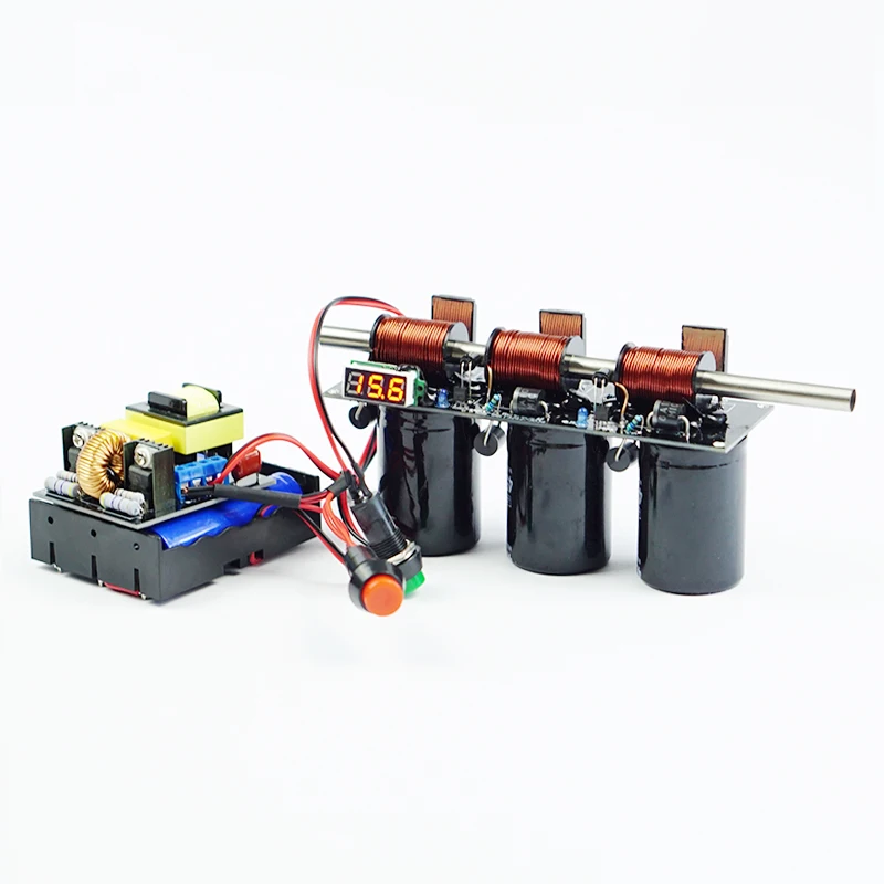
In the photo below, you can see what the end result of the tinkering will look like. In the left opening of the barrel you put one of the metal bullets provided. With the red pushbutton, charge the electrolytic capacitors until the voltmeter indicates a voltage of 425 V. Using the green pushbutton, eject the bullet.
 |
| The completely assembled kit. (© Industrial Parts Store) |
The circuit board
The PCB is of course double-sided with plated through holes. Both sides are shown in the picture below. As you will notice, all descriptions are in Chinese.
 |
| Both sides of the PCB. (© 2023 Jos Verstraten) |
The high voltage electrolytics
As the picture below shows, these are hefty juggernauts with a capacity of 680 μF and an operating voltage of 450 V. They are specially manufactured to be able to deliver a very large peak current so that as much power as possible is transferred to the coils in as short a time as possible.
 |
| The supplied high voltage electrolytics. (© 2023 Jos Verstraten) |
The coils
These are wound from 0.8 mm thick winding wire, have a length of 29 mm and a diameter of 21 mm. The central hole has a diameter of 8 mm.
 |
| The provided coils. (© 2023 Jos Verstraten) |
The high voltage generator
For some reason, it comes completely assembled with this kit. The PCB measures 50 mm by 60 mm and converts an input voltage of 12 Vdc into an output voltage of about 450 Vdc. The input peak current is 15 A, the output current 100 mA. From the dimensions of the heatsink, it immediately becomes clear that you cannot continuously leave this module on. A power of 12 V times 15 A equals 180 W and that cannot be dissipated by such small heatsinks. Hence, the kit comes with a push button that interrupts the positive power supply connection. You press this button until the electrolytics are charged to their working voltage and then release this button so that the module is only switched on for a very short time when you fire a shot with the coil gun.
 |
| The supplied high voltage generator. (© AliExpress) |
You will notice that there are no electrolytic capacitors on this PCB. Just hanging the oscilloscope on the output confirms the suspicion that the PCB does not deliver a nice DC voltage, but only a rectified AC voltage. For this application this is no problem at all, because the heavy electrolytics act as a smoothing component! You can see the unloaded output voltage, the blue trace shows the GND level.
 |
The output voltage of the HT generator. (© 2023 Jos Verstraten) |
The digital voltmeter
As can be seen from the picture below, the voltmeter is a PCB reduced to the bare minimum from which come three wires for power, ground and the voltage to be measured. Unfortunately, again all the data is missing, so we hope that our estimation that the yellow wire is the input, the red is the plus and the black is the GND is correct.
 |
| The miniature voltmeter. (© 2023 Jos Verstraten) |
The schematic of the coil gun
Because of the double-sidedness of the PCB and the black silkscreen, it is not easy to convert the trace pattern on the PCB into a schematic. We made the best of it and came up with the result below. This is the schematic of the second stage which is the most comprehensive. The first and third stages do not have certain parts of this schematic.
The electrolytic capacitor C1 of 680 μF and 450 V is charged from the +450 V through the diode D1. This is not just any diode, but a 6A10. It has a peak current of 250 A, a continuous current of 6 A and a reverse voltage of 1,000 V. Across the capacitor is a small blue LED D2 via a series resistor of 5.6 MΩ. This blue LED lights up when the electrolytic capacitor is charged and provides a discharge path when the circuit is de-energized.
So remember: when the blue LED is on, the PCB cannot be touched!
The coil L1 is mounted around the barrel of the coil gun. The coil is accompanied by a diode D3 that ensures that voltage spikes created across the coil are completely suppressed. That too is not just any diode, but an FR607. That is a fast recovery rectifier with a reverse voltage of 1,000 V, a peak current of 300 A and a continuous current of 6 A. The capacitor C1 is discharged across the coil L1 via the thyristor D4. That too, had you expected anything else, is not an ordinary thyristor but a 70PT16B. It can switch a peak current of no less than 550 A and can handle 70 A continuously. The reverse voltage may be a maximum of 1,600 V.
 |
| An attempt to reconstruct the schematic. (© 2023 Jos Verstraten) |
In the first stage, this thyristor is ignited via the green pushbutton S1 and resistor R2 of 100 Ω. In the second and third stages, the gate current is provided by the transistor T1 and the resistor R4. To understand this mechanism, look to the far right. There you will see an infrared LED D6, which is continuously energized through the resistor R6. This LED is at one side of the barrel and is radiating through a hole in the barrel to the phototransistor T2. When the barrel is empty, the IR light falls on the transistor and it starts to conduct. The collector is thus pulled to the GND potential. As a result, the base of T1 also goes to that potential and this transistor shuts down. The gate of the thyristor is not driven. However, when the bullet shooting through the barrel passes the light barrier, the light beam is momentarily interrupted. The transistor T2 goes to cut off. The transistor T1 now receives base current through the resistor R5 and starts to conduct. As a result, the red LED D5 lights up briefly.
A second consequence is that the gate of the thyristor D4 is connected to the 100 Ω resistor R4 via the conducting T1.
The proper operation of the coil gun depends on where you drill two holes through the barrel and mount the light barriers D6/T2. The red LEDs D5 help you align these parts properly. If this is not done properly the LEDs will light up.
Construction of the coil gun
Mounting the PCB
The easiest order when mounting the PCB is as follows:
- 2 x 10 kΩ resistors, horizontal
- 2 x 2 kΩ resistors, horizontal
- 3 x mini-LEDs blue, pay attention to polarity!
- 2 x mini-LEDs red (next to the thyistors), pay attention to polarity!
- 2 x transistors S8050
- 2 x 2 kΩ resistors, vertical
- 3 x 5.6 MΩ resistors, vertical
- 3 x diodes 6A10, pay attention because there are six almost identical looking diodes, so check the code printed on the diode
- 3 x thyristors 70PT16B, with the metal part facing inwards
Now turn the PCB over and assemble:
- 3 x diodes FR607
- 3 x electrolytics 680 μF, 450 V, note the polarity
There should be at least 2 mm space between the PCB and the bottom of the electrolytics. Now turn the PCB over again and press the protruding pins of the electrolytics and the connecting wires of the diodes as flat as possible on the PCB surface and solder them in place.
Assembling the coils
The connecting wires of the coils are lacquered and this lacquer is not solderable. You must therefore remove the lacquer thoroughly with a sharp knife or with special pliers available on the market for this purpose. Carefully tin the bare copper wire ends with a thin layer of tin. Then slide the three coils onto the barrel making sure that the barrel sticks out about 1 cm on the left side.
 |
| Removing the lacquer from the winding wire. (© 2023 Jos Verstraten) |
Pay close attention that the three coils are wound in the same direction. Moreover, the outer connecting wires should be on the side of the PCB where the heavy diodes 6A10 are soldered. Now mount the three coils on the PCB, making sure that there is at least 2 mm distance between the outer windings and the soldered pads on the PCB. Turn the PCB over and solder the six connecting wires of the coils.
Mounting the two light barriers
The picture below shows how to mount the two (black) light-sensitive transistors and the two (transparent) IR LEDs around the barrel. Bend the connecting wires at a 90-degree angle, but when doing so, make sure that the flattened side of the housing ends up on the right side. You can identify this by the silkscreen printed on the PCB. Assemble the parts as shown, the tops of the parts should end up in the center of the barrel. Turn the PCB over and solder the eight wires in place.
 |
| Assembly of a light barrier. (© 2023 Jos Verstraten) |
Next, mark two pencil marks on the barrel where the light barriers are located against the barrel. Carefully pull the barrel out of the three coils and drill two 3 mm holes through the barrel at the locations of the marks. Deburr the holes well on the inside of the barrel. Refit the barrel into the three coils and rotate the barrel so that the holes exactly coincide with the top of the phototransistors and IR LEDs.

Assembling the voltmeter
Unsolder the three connecting wires and replace them with three wires cut from the resistors you have already soldered to the PCB. Then mount the meter on the lower left corner of the board, next to the blue LED, and solder the three wires to the other side of the board.
 |
| Assembly of the voltmeter. (© 2023 Jos Verstraten) |
The PCB is now ready
The two pictures below give an impression of the completely assembled and soldered PCB.
 |
| The front side of the PCB. (© 2023 Jos Verstraten) |
 |
| The back side of the PCB. (© 2023 Jos Verstraten) |
Final assembly and inter-wiring
The battery holder
Take the battery holder and solder a wire between the minus of the first cell and the plus of the second cell. Do the same between the second and third cells. You are now left with two free solder tabs that form the plus and minus of the coil gun's 12 Vdc power supply.
The wiring between the parts
In the figure below, we have presented the wiring between the various components:
A black wire from the minus of the power supply to the -12 V on the coil gun PCB.
A black wire from the minus of the power supply to the -12 V on the high voltage PCB.
One red wire from the plus of the power supply to the +12 V on the coil gun PCB.
A red wire from the plus of the power supply to the red push button.
One red wire from the red push button to the +12 V on the high voltage PCB.
A black wire from the -450 V of the high voltage board to the -450 V on the coil gun board.
One red wire from the +450 V of the high voltage PCB to the +450 V on the coil gun PCB.
Two green wires from the green pushbutton to the solder pads above the 100 Ω resistor on the coil gun PCB.
 |
| The interconnecting wiring. (© 2023 Jos Verstraten) |
The coil gun in action
After connecting the power supply, the two red LEDs should not be lit. If one or both are lit, it means that one or both light barriers are misaligned. Then rotate the barrel until the drilled holes are exactly aligned with the tops of the IR LEDs and the phototransistors. Once both red LED' are extinguished you can start firing a test shot.
Push one of the metal bullets into the left opening of the barrel. Make sure the bullet stays in that place by, for example, drilling a very small hole in the bottom of the barrel at that location for the bullet to rest in. Point the barrel toward an open cardboard box that you place about thirty centimeters in front of the right opening of the barrel.
Put on a pair of safety glasses. Take the green pushbutton in your left and the red pushbutton in your right hand. Press the red pushbutton. You will see the voltage rise on the digital voltmeter. When the voltage has risen to 425 V, release the red push button. Now briefly press the green push button. When you have successfully completed construction you will hear a soft bang and the bullet will be shot into the box at an amazingly high speed.

Tri-stage Coil Gun Demo Kit