|
For about eight euros, buy this kit of a miniature Christmas tree in which 36 LEDs flash. It is easy to solder and you can power it from a 5 V mains plug power supply. |
Introduction to the CTR-30 kit
Manufacturer, suppliers and prices
The kit's manufacturer is EEQKIT, which markets it under the code CTR-30. The kit is sold by dozens of suppliers who advertise it for sale on AliExpress under a variety of fancy names. We found one supplier, PROTECTION Store, which offers it for € 2.85 plus € 2.32 shipping. However, the delivery time is then more than one month! Our regular reliable supplier Banggood has it available for € 8.50 including shipping. It can even be bought via bol.com from AZ Delivery, but then you pay € 9.99 for it.
The fully assembled kit
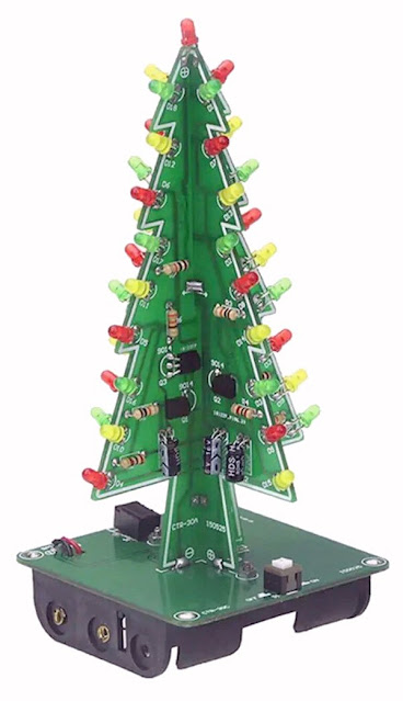
You can see the result of a few hours of not too difficult crafting in the photo below. The Christmas tree is 12.5 cm high and has a base board measuring 6.0 cm by 6.0 cm. You can power it from three type AAA 1.5 V batteries or use the included USB cable and power it from a standard 5 V mains power supply.
 |
| The fully assembled kit. (© Banggood) |
Delivery of the kit
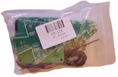
As we are used to from such deliveries from China, the components are squeezed together in a far too small plastic bag. Fortunately, there are no fragile parts inside! No manual is included, but several building descriptions can be found on the internet. We will come back to those.
 |
The delivery of the kit. (© 2023 Jos Verstraten) |
The supplied components
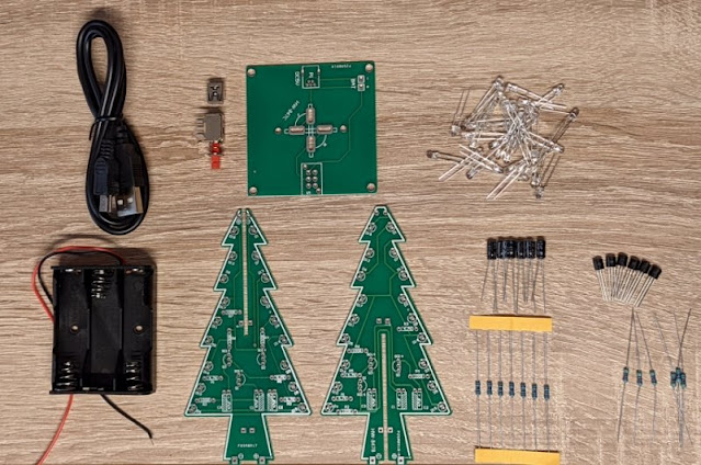
In the picture below, all the components present in the kit are neatly displayed. There is nothing to criticise about the quality of the components supplied, which is good. However, in some kits, all the LEDs supplied are transparent and then you cannot see what colour they emit. In other kits, the LEDs come in red, yellow and green colours.
 |
| The contents of the kit. (© AZ-Delivery) |
The manual
We found four different manuals for this little kit. The one from EEQKIT itself is quite brief. The most comprehensive one is compiled by IC-Station and has no less than 37 pages. We have included it on our account at https://archive.org and you can download it here:
The three PCBs
The Christmas tree consists of two identical circuits, built on two almost identical PCB. Once these PCBs are fully soldered, you need to slide them together and mount them on the lower PCB. Even such a cheap kit comes with double-sided, metallised PCBs.
 |
| The three PCBs of the Christmas tree. (© 2023 Jos Verstraten) |
The diagram of the LED Christmas tree
We have redrawn the schematic of one PCB with sPlan, see figure below. It is quite an ingenious circuit. The standard schematic of an astable multivibrator with two transistors has been extended with an extra stage. Basically, three RC networks C1/R3, C2/R5 and C3/R1 control the base of the transistors. Such a capacitor puts a negative voltage on the base at some point in the cycle. That negative voltage flows through the resistor to the positive power supply. The moment the voltage at the base rises to about +0.65 V, the relevant transistor starts to conduct. The collector voltage goes to zero, the LEDs in the collector light up. The negative voltage jump on the collector creates the negative voltage on the base of the next transistor. In this way, the system maintains itself and the three transistors Q1, Q2 and Q3 take turns to conduct.
Since the three capacitors and resistors have identical values, the three transistors are going to conduct for the same amount of time. However, you can play with those conduction times by giving the capacitors or resistors different values.
In series with the LEDs are resistors R2, R4 and R6 that limit the current. The three various values of those resistors should ensure more or less equal light output from the red, green and yellow LEDs. Theoretically, it is not recommended to connect LEDs in parallel because they do not all have identical voltages and so one will burn much brighter than the other. But from the practice of this schematic, you won't be bothered by this!
The red LED D19 is at the top of the Christmas tree and is always lit. D19 and R7 are present on only one of the two PCBs.
 |
| The schematic of the CTR-30 kit. (© 2023 Jos Verstraten) |
Building the kit
Soldering the PCBs
There is not much to write about building the LED Christmas tree. Of course, you should pay attention to the correct positioning of the cathode and anode of the LEDs. You won't see this clearly on the PCB itself, but it is clearly described in the manual you can download from this page.
If you are unlucky that your package contains LEDs with transparent housings, you should test the colour by connecting them, with a series resistor of 10 kΩ, to a voltage of about 5 V.
 |
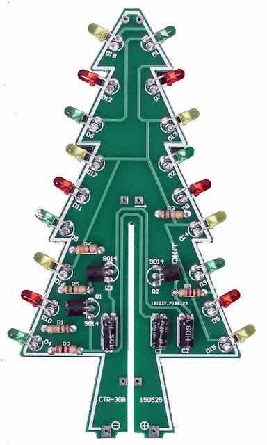
| One of the two fully assembled PCBs. (© AliExpress) |
Do not simply follow all the steps in the manual blindly!
The manual states that you should slide the two mounted PCBs together and connect them with solder in eight places. As a final step, you should then push that PCB combination into the slots of the bottom PCB and solder the PCBs together in eight places. As we had not put the two PCBs together at exactly right angles, this last step did not work.
So we advise you to slide the two PCBs together, but not solder them to one another yet. Push the PCBs into the slots of the base PCB, which always works now, and then start soldering all PCBs together in the prescribed sixteen places.
To give you an idea of the visual effect of this LED Christmas tree, we copied a sequence from a YouTube video:
The power supply
As shown in the first photo published in this article, you can mount a battery holder under the base board. Three type AAA batteries fit in there. Although the LEDs only require a current of 20 mA, we still recommend powering the Christmas tree from a 5 V mains supply via the USB cable supplied. That will save you a lot of battery waste!
If you are powering via the USB cable, you do have to remove the batteries from the holder!

LED Christmas tree kit


