|
For less than two euros, you can buy this kit of an electric car that follows a black track on a white background. A nice kit to get the youngsters interested in electronics! |
Getting to know the Sheng Yang D2-1
The finished kit
In the picture below you can see the end result of an hour of tinkering. A battery powered car with the dimensions 10.5 cm by 8.5 cm by 4.5 cm. The car has only two rear wheels, each driven by its own motor. The front rests on a rounded metal nut that glides over the table. Next to this nut are two red LEDs that brightly illuminate the white surface of the table. Two LDRs (light-sensitive resistors) detect the reflected light and control the two motors via a very simple circuit.
 |
| The final result of the construction of this car. (© Sheng Yang) |
What is a tracking line car?
The D2-1 is called a 'tracking line car' by the manufacturer Sheng Yang. This means that you need at least a light coloured flat surface and you need to make a track with black tape with a width of about 15 mm. Avoid sharp turns, because the car cannot follow them. If you then place the car on this track with the tape in the middle between the two LEDs and operate the push button, the D2-1 should zigzag along this track. To give you an impression we have copied a part of a video made by RC LIFE:
Where to buy and what does it cost?
The D2-1 is apparently a very popular kit because you can order it from dozens of mail order companies via AliExpress and also from Banggood. Just do some extensive Googling to find the lowest price! At the time of writing, the cheapest offer came from the Aideepen Direct Store on AliExpress who offered it for the incredible price of € 1.78 with € 2.61 shipping costs to the Netherlands. But that may be completely different by the time you read this article. We bought our kit from our regular supplier Banggood, which delivers very quickly.

The delivery of the kit
The delivery of the kit
As usual with such cheap Chinese orders, all parts are crammed into a plastic bag that is too small. This is again packed in the well-known black plastic in which a lot of Chinese shipments are delivered. It fits in the letterbox, so you do not have to stay at home to receive it.
 |
| The packaging of the kit. (© 2022 Jos Verstraten) |
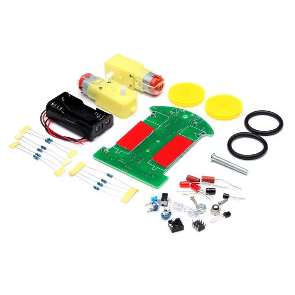
The contents of the kit
In the picture below you can see what you get for those two euros. The two yellow parts below the battery holder are the two motors. They are equipped with a gearbox that takes care of the necessary reduction of the speed and a shaft, perpendicular to the motor-axis, on which you have to screw the wheels with rubber tyres. The three grey rectangles under the resistors are three double-sided adhesive foils that you must use to attach the motors and the battery holder to the PCB. That seems rather unreliable, but in practice it is not. The three parts are firmly attached to the PCB.
 |
| The contents of the kit. (© 2022 Jos Verstraten) |
The manual
That's a nonsensical piece of paper in Chinese! However, after a Google search, we found a good twelve-page manual in English, which we saved to our own Google cloud and which you can download here:
➡ Tracking_Line_Car_Manual.pdf
➡ Tracking_Line_Car_Manual.pdf
The PCB for the tracking line car
In the picture below, you can see both sides of the PCB. It is single-sided, so the holes are not metallised. Moreover, the holes are rather large and the pads rather small, which you have to get used to when soldering. The solder does not flow smoothly into the hole, but stays on the pad.
 |
| The two sides of the PCB. (© Sheng Yang) |
The schematic of the D2-1
In the figure below we have drawn the complete and rather peculiar schematics of this 'intelligent' car. Curious, because there are certain things which, in theory, are not possible at all. The heart of the circuit is IC1, a double comparator of the type LM393. This circuit has an open collector output that is grounded if the voltage on the negative input is greater than the voltage on the positive input. If the voltage at +IN is greater than that at -IN, the output becomes high impedant. These outputs control the bases of the transistors Q1 and Q2 via resistors of 10 Ω (!). The emitters of these semiconductors are connected to the plus of the power supply. It seems that, when the output transistors in the comparators are driven into saturation and the outputs thus go to zero, a much too large base current flows in the transistors. Nevertheless, the circuit works very well in practice. Measurements show that the outputs of the LM393 do not go to zero, but remain at about 1.2 V with a supply voltage of 2.8 V from the two batteries.
 |
| The schematic of the model. (© 2022 Jos Verstraten) |
The way the car follows the black line is also a bit strange. The LEDs D4 and D5 are emitting perpendicularly downwards. The LDRs R13 and R14 receive the reflected light. If the car drives over a white table, the LDRs will receive the maximum amount of reflected light and their resistance will be minimal. The voltage at the nodes R1/R7 and R2/R8 will then be minimal. These voltages drive the four inputs of the two comparators, but in 'reverse phase'. R1/R7 goes to the positive input of IC1A and to the negative input of IC1B. The reverse is true for R2/R8. Since the voltages at both junctions are obviously never exactly the same, one of the two motors would always be driven in this situation and the car would drive in circles. Nevertheless, with the two adjustment potentiometers R1 and R2 you can set a fairly large area where the two motors start to turn and the model drives a relatively straight course. That is strange, or are we overlooking something?
If you start from this situation, i.e. let the car drive on a white table, and point the model to a line made of 15 mm wide black tape, the car will in most cases follow this black tape neatly. This can, of course, be fully explained from the diagram. If one of the LDRs is placed above the tape, the amount of reflected light will decrease significantly, the resistance of the LDR will increase and the voltage at the corresponding junction between both resistors will also increase. One of the comparators is then unambiguously sent to 'L' and the other to 'H'. The result is that one motor starts running and the other stops and the model is controlled to follow the black tape.
When following the tape, it is easy to see how such a control system works. Both motors are steered in turn, so that the model zigzags from left to right and from right to left following the tape.
The construction of the D2-1 tracking line car
The component side of the PCB
That's child's play, ten resistors, two electrolytic capacitors, two transistors, two LEDs, two adjustment potentiometers, a switch and an IC are soldered just like that. Leave the battery holder in place for now.
Next, screw the long 35 mm M4 bolt onto the PCB with the nut provided and attach the locking nut with the half-round head to the bolt.

The copper side of the PCB
On this side you must first mount the two red LEDs and the two LDRs. You should do this in such a way that the heads of these parts are exactly 5 mm lower than the locking nut, see the picture below.
 |
| Mounting the LEDs and the LDRs. (© Sheng Yang) |
Next, solder flexible wires of about four centimeters to the two solder tabs of the two motors. Stick two of the three pieces of double-sided adhesive film on the PCB and press the motors onto these strips. Pay attention to the position, see the photo below. Solder the four wires to the four pads without holes. You should do this in such a way that you can swap the two wires without any problems. After all, at this moment you do not know whether the motors rotate in the right direction. Attach the two wheels to the shafts of the motors with the small screws.
 |
| Mounting the two motors. (© Sheng Yang) |
The final assembly
Stick the last two-sided adhesive strip on the component side of the PCB in the place where the battery holder will be. Press it firmly onto the strip. Lead the two wires of the holder through the one hole of the PCB and solder the wires to the + and - pads on the copper side of the PCB.
Playing with the D2-1 tracking line car
Adjusting the potentiometers
Turn one of the two adjustment potentiometers to the middle position. Place two 1.5 V batteries in the holder and press the switch. With one hand, push the model onto a white table so that the wheels turn freely in the air, but the locking nut of the bolt rests on the table. One of the motors will now turn. Turn the slider of the other potentiometer until the second motor also starts to turn.
Check that both motors rotate in the same direction. If that is not the case, just swap the two wires of the wrongly turning motor on the PCB.
Now put the model on the table and check if the car follows a fairly straight path.
Making a track
You can use a roll of black insulation tape. Set out a track with not too sharp bends. If you now put the car on a straight part of this track, the car will follow the track nicely.

Tracking-Line-Intelligent-Robot-Car