|
This is a lovely nostalgic kit that wouldn't look out of place in an 'elektor' from the 1980s. However, it is an ideal project to teach people how to solder and introduce them to digital electronics. |
Introduction to the digital CMOS clock kit
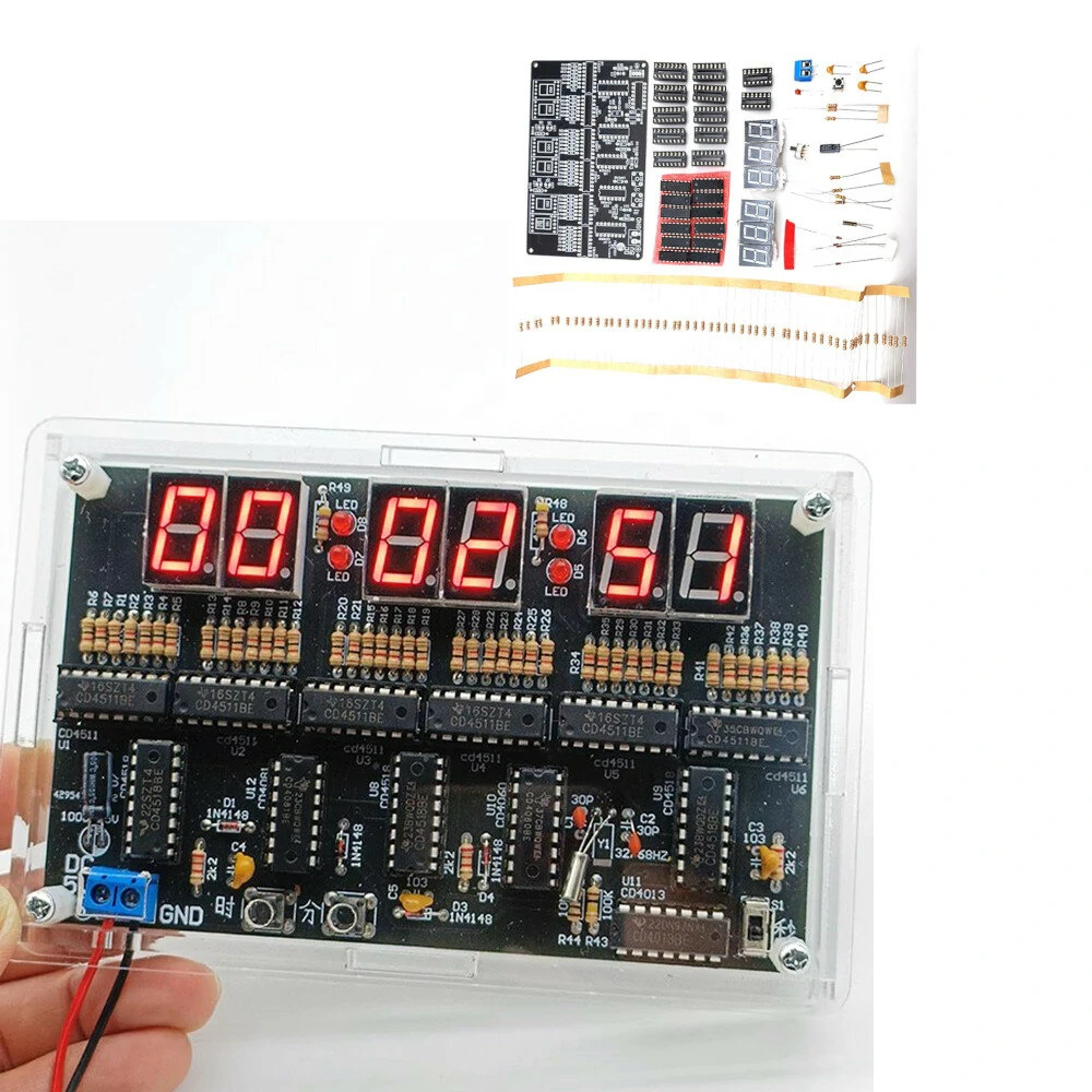
The result of a few hours of soldering
In the picture below, you can see the result of a few hours of soldering. A PCB stuffed with twelve CMOS ICs, measuring 12.9 cm by 7.9 cm. Those elaborate 1980s electronics result in a 24-hour clock that you can power from a 5.0 Vdc supply and is driven by a 32.768 kHz tuning fork resonator. From this oscillator, a one-second pulse is derived that drives the clock's digital electronics. These electronics count the oscillator's pulses in a special way. The six very bright red seven-segment displays show the number of pulses counted in 'hours-minutes-seconds' format. The clock counts up to '23-59-59' and then jumps back to '00-00-00'. Between the displays are four red LEDs that flash at one-second intervals.
Two push buttons allow you to set the hours and minutes and with a slide switch you can block the one-second pulse. So you can also use this clock as a chronometer. Turn slide switch S1 to 'OFF' when the seconds display jumps to '00'. Set the hour and minute displays to '00' as well. At the time when the stopwatch should start running, set the slide switch S1 to 'ON'. The clock will then count the hours, minutes and seconds until you set the slide switch back to 'OFF'.
 |
| The end result of this kit. (© Banggood) |
Manufacturer, suppliers and price
The manufacturer of this kit cannot be traced, although it is clear that it is a very popular kit in China. You will find a lot of suppliers on AliExpress and it is also on sale at Banggood. Two versions are offered. The cheapest one only contains the PCB with all components, while the more expensive one additionally provides an enclosure consisting of six transparent perspex panels.
For the cheap version, you pay € 10.82 at Banggood and € 8.62 at AliExpress, including shipping. For the more expensive version, the prices are € 13.05 and € 11.82 respectively. Funny thing is that the same kit is also offered via bol.com for.... € 36.00!
A rock-bottom price
Surely it should be emphasised again that Chinese suppliers supply such diy kits at an absolute rock-bottom price. If you order just the twelve CMOS ICs from Conrad Electronic, you pay € 19.05 for them!
Delivery of the kit
For such prices, we do not expect much attention to the way the kit is shipped. We are therefore very surprised to find that there is even a plastic box in which all components are safely stored. So no bent pins on IC sockets and ICs this time!
 |
| The delivery of this kit. (© 2024 Jos Verstraten) |
The parts supplied
These are of excellent quality. It should be noted that even sockets are supplied for the twelve CMOS ICs. The 32.768 kHz tuning fork resonator is in a metal housing with no description. So it is impossible to check which type is supplied and how accurate this part is. This is of utmost importance, because the accuracy of the resonance frequency of this part determines whether the clock keeps running right or not.
 |
| The supplied parts. (© 2024 Jos Verstraten) |
The parts for the housing
If you order the most expensive option, for an extra three euros you will get the parts below, which you can use to assemble a transparent housing around the PCB. Holes have been milled in the front panel for the push buttons, power connection and slide switch. The perspex panels have a brown paper cover on both sides, which you can remove with some effort.
 |
| The parts for assembling the case. (© Banggood) |
The manual
Following Chinese tradition, the kit is delivered without a manual. However, after some searching on the internet, we did find a manual in PDF format, which we saved on our account at 'archive.org':
The printed circuit board for the circuit
As with all cheap Chinese kits, there is nothing wrong with the PCB: double-sided, metallised, with solder mask and silkscreen. The component side of this PCB is shown in the picture below. The other side is completely black, so there is nothing to see on it.
 |
| The component side of the PCB. (© 2024 Jos Verstraten) |
The electronics in this digital CMOS clock
The 32.768 kHz tuning fork resonator
Modern clock building kits use synchronised operation, where a time code signal is fetched from your provider via wifi to keep the clock in sync with official time. There is no such complicated modern technology in this old-fashioned kit. The most important part of any non-synchronised clock is, of course, the time pulse generator. In this package, a so-called tuning fork resonator is used. In this case, this tuning fork vibrates at a frequency of exactly 32.768 kHz.
Tuning fork resonators derive the very low resonance frequency from their specific shape. Of course, these parts are not called 'tuning fork' for nothing. Indeed, the shape of the resonator is entirely similar to the shape of the well-known metal tuning forks, which are used for tuning musical instruments and which, according to some believers, also have all kinds of beneficial effects on the body and mind. The picture below shows the typical shape of such a fork, fitted with evaporated electrodes and mounted in a housing.
 |
| The interior of the tuning fork resonator. (© Wikimedia Commons) |
The operation of the resonator
A tuning fork resonator works like a crystal oscillator. Certain natural materials such as quartz exhibit a piezoelectric effect. If you put an electric voltage across the material it will be compressed or stretched. This phenomenon also works in reverse: mechanical deformation generates a voltage. So the material reacts to an alternating electric field by performing a periodic movement. The frequency at which this happens depends on the physical properties of the material, especially the shape and thickness of the slice.
Because of this property, it is possible to use a material with piezoelectric properties to generate an alternating voltage with a very constant frequency. If you put a broadband noise voltage across a small slice of material with such properties, the slice will start amplifying one frequency from this signal. This is the frequency at which the slice will vibrate to its maximum. Indeed, this vibration will create a fairly large voltage across the slice whose frequency is equal to the resonant frequency of the resonator.
Why 32.768 kHz?
Why choose the, at first sight, rather odd frequency of 32.768 kHz? One can derive a signal with a frequency of exactly 1 Hz from this frequency using some standard flip-flops. As you no doubt know, a flip-flop allows you to divide the frequency of a square wave signal exactly by two. Just count where we end up assuming a signal with a frequency of 32.768 kHz:
- output flip-flop 1: 16.384 kHz
- output flip-flop 2: 8.192 kHz
- output flip-flop 3: 4.096 kHz
- output flip-flop 4: 2.048 kHz
- output flip-flop 5: 1.024 kHz
- flip-flop 6 output: 512 Hz
- output flip-flop 7: 256 Hz
- flip-flop 8 output: 128 Hz
- flip-flop 9 output: 64 Hz
- flip-flop output 10: 32 Hz
- flip-flop output 11: 16 Hz
- flip-flop output 12: 8 Hz
- flip-flop output 13: 4 Hz
- flip-flop output 14: 2 Hz
- output flip-flop 15: 1 Hz
This technique is also used in this kit to generate a very accurate and stable one-second pulse.
The full schematic of this CMOS clock
What can be done today with a single IC, a microcontroller, used to require a handful of ICs in the TTL and CMOS era. So too in this design, where 12 CMOS ICs are needed to build the 24-hour clock. We have split the schematic into two parts, so that you can still somewhat read it in your browser window.
 |
| Part 1 of the schematic diagram. (© Banggood, edit 2024 Jos Verstraten) |
 |
| Part 2 of the schematic diagram. (© Banggood, edit 2024 Jos Verstraten) |
Note
Please note that the numbering of the components in the above schematic diagrams does not necessarily correspond to the numbering on the PCB!
The one-second generator
The 32.768 kHz tuning fork resonator is included in the oscillator circuit of an IC designed specifically for this purpose. That is IC10, a CD4060BE. This circuit contains an oscillator and fourteen frequency dividers. The oscillator consists of the tuning fork resonator, resistors R48 and R49 and capacitors C5 and C6. On the output Q14 of the CD4060BE, a nice rectangular pulse with a frequency of 2 Hz is produced.
IC11 is a CD4013BE, an IC containing two independent D flip-flops. One of those flip-flops is configured as a frequency divider. At the output Q of this IC, a neat pulse with a frequency of 1 Hz is generated, i.e. with a period of one second.
The clock circuit
The CD4518BE is a double decimal counter. Three such ICs (IC9, IC8 and IC7) are used to count seconds, minutes and hours. These ICs have external feedback so that IC9 and IC8 count up to 59 and IC7 counts up to 23. This external feedback is achieved through the four gates of IC12, a CD4081BE. This IC contains four AND gates with two inputs each. The outputs of those gates control the resets of the counters when the correct counter contents are present, so that they jump back to zero and the counting can start again. The outputs of IC12D and IC12C additionally control the count inputs EN of the subsequent counters so that they add up to one unit.
The code converters and display controls
The contents of the counters in the CD4518BE ICs in BCD-encoded on the outputs Q0, Q1, Q2 and Q3. These outputs control the data inputs of six pieces of CD4511BE. These are BCD-decoders/display-drivers. The CD4511BE converts the BCD-code on its inputs to control signals for the seven segments of a seven-segment LED display. The 1 kΩ resistors limit the current through the segments.
Setting the clock by hand
To manually set the hours and minutes display to the desired value, additional pulses are presented to the EN inputs of IC7A and IC8A via pushbuttons S1 and S2. The diodes D1-D2 and D3-D4 form simple OR gates that allow the EN inputs to be controlled either from the previous counters or from the pulses you offer with the pushbuttons.

The LEDs
The four LEDs LED1 to LED4 are driven from the one-second pulse via the series resistors R43 and R44 and thus flash when the clock is operating.
The power supply
The circuit can be powered from any stable 5 Vdc power supply capable of delivering a current of about 100 mA.
Building the circuit
Assembling the circuit board
Below we give the correct order for soldering all components on the PCB:
- 42 pieces of 1 kΩ resistors between the displays and the CD4511 chips. For some reason, 50 are supplied, but there are no more than 42 on the PCB.
- 3 pieces of 2.2 kΩ resistors.
- 2 pieces of 470 Ω resistors.
- 1 piece of 100 kΩ resistor.
- 1 piece of 10 MΩ resistor.
- 4 pieces of 1N4148 diode, pay attention to the cathode ring!
- 4 pieces of red LEDs, the longest connecting wire must be in the hole marked '+' on the PCB.
- 3 pieces of 100 nF capacitors (code 103).
- 2 pieces of 30 pF capacitors (the manual says 22 pF).
- 1 tuning fork resonator of 32.768 kHz, this rests flat on the PCB.
- 2 pushbuttons S1 and S2.
- 10 pieces of IC sockets with 16 pins, note the identification notch corresponding to pin 1.
- 2 pieces of IC sockets with 14 pins, idem.
- The slider switch S1.
- 6 pieces of seven-segment displays, the side with the description pointing to the side where the IC sockets are.
- The two-pole PCB terminal block, obviously with the holes facing outwards.
- The 100 μF electrolytic capacitor, the longest connecting wire should be in the PCB hole with the '+' symbol. This component should also rest flat on the PCB.
This ends the soldering work on this PCB. Finally, you can carefully press the twelve CMOS ICs into the sockets. Make sure that all pins are in the holes and not bent under the IC body.
The picture below shows the end result of a few hours of pleasant hobbying.
 |
| The completely assembled PCB. (© 2024 Jos Verstraten) |
Final assembly and testing of the CMOS clock
Connecting the power supply
Connect a 5 Vdc power supply to the terminal block, obviously paying attention to the position of the plus and minus. If all went well, all displays should now first go to zero and after one second the counting of seconds should start. If nothing happens, move slide switch S1 to the other position.
We measured the current consumption of the clock. It is between 60 mA and 85 mA, depending on the amount of segments that light up.
Accuracy
The proper functioning of such a clock obviously hinges on the accuracy of the one-second clock pulse. The picture below shows what that pulse looks like. The blue trace shows the zero level. We measured the pulse period with our frequency/period meter PM6669 from Fluke. Over a period of one day, the pulse duration varied between the two values below:
- 0.999,762,6 second
- 1.000,047,2 second
The positive and negative deviations are probably caused by variations in room temperature. That, over one day, there is both positive and negative deviation from the exact value of 1.000,000,0 seconds is favourable. Both deviations largely cancel each other out. This proves that the tuning fork resonator provided is very accurate. This is not surprising, as such a component is in every electronic wristwatch and they almost all run concurrently with the official time.
 |
The one-second pulse on switch S1. (© 2024 Jos Verstraten) |
Mounting the PCB in the enclosure
If you have ordered the more expensive option, you now need to build the PCB into the enclosure.
- First carefully remove the brown protective film from the perspex panels.
- Screw the nylon spacers to the back of the front panel using four of the short bolts provided.
- Snap the four side panels into the front panel.
- Place the PCB on the four spacers.
- Click the back plate into the four side panels.
- Screw the back plate and PCB into the spacers with the four long bolts.
It is unclear what the four supplied nuts are for.
 |
| The fully completed digital CMOS clock. (© 2024 Jos Verstraten) |

Digital CMOS clock kit