|
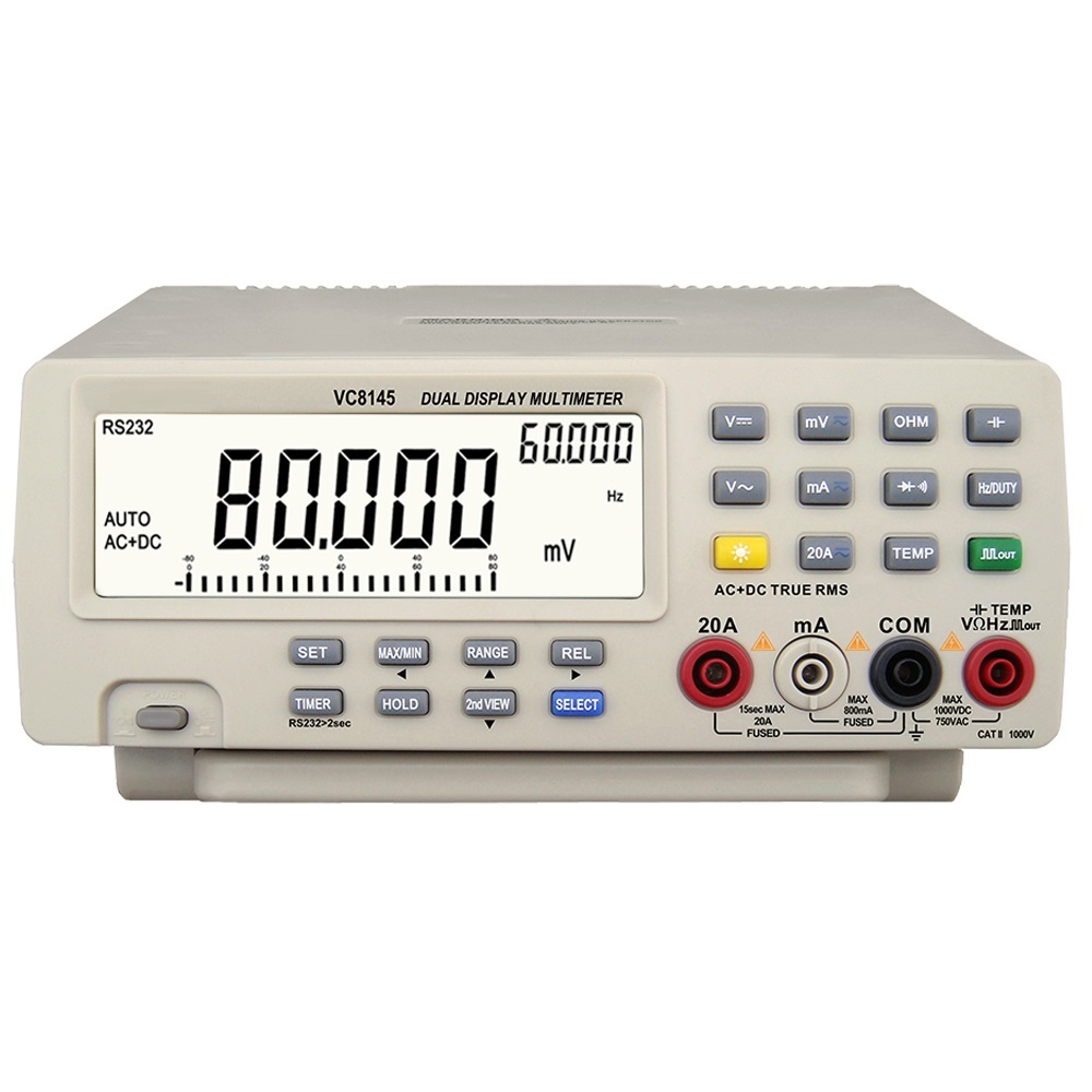
The DM8145, also sold as VC8145, is an inexpensive desktop multimeter with a reading of up to 80,000 counts and a lowest voltage range of 80 mV. The meter has extras usually found only on much more expensive devices. |
Getting to know the DM8145/VC8145
Manufacturer, suppliers and prices
Eye-catching features of the DM8145
The device is housed in a large, sturdy and heavy case. It measures 22.0 cm by 26.0 cm by 8.2 cm and weighs 1.3 kg! The meter is operated entirely by twenty pushbuttons which, thanks to the heavy weight, can be easily operated with one finger without slipping. The digits of the primary readout on the LCD display are 2.0 cm high. The secondary readout in the top right corner of the display is also easy to read with a digit height of 8.0 mm. Instead of the secondary numeric readout, you can select a bargraph display for some measurements, which responds extremely quickly to variations on the measured quantity. However, this linear scale has a very low resolution of only 23 steps. The yellow pushbutton allows you to switch on the display's excellent backlighting.
For direct and alternating voltage, the DM8145 offers a lowest full scale range of 79.999 mV. Another notable feature is that for voltages, you can switch to dBm measurements with a range of ±80.00 dBm where you can select the reference resistance from twenty values between 4 Ω and 1,200 Ω. The two numeric displays allow you to measure two parameters of the measured quantity together, for example magnitude and frequency. The DM8145 also offers the option of displaying only the positive or negative peak value.
 |
| The DM8145 with the bracket folded out. (© Banggood) |
Of course, you can also measure capacitors. One limitation of this meter is that it can only measure up to 100.00 μF! When it comes to currents, the DM8145 also has a limitation: the lowest measurement range is 80.000 mA. On the other hand, you can measure currents up to 20.000 A for a maximum of 15 seconds. This measuring range is protected by an internal ceramic fuse of 13 A (5 mm x 25 mm). The 80.000 mA and 800.00 mA measuring ranges are protected by a normal 800 mA glass fuse (5 mm x 20 mm), conveniently incorporated in the 'mA' connection socket. So there is no need to unscrew the meter if you blow this fuse. The 'burden' voltage when measuring currents is up to 800 mV.
The measurement range for resistances goes from 800.00 Ω to 80.000 MΩ full scale. However, there is a special 'Hi Resistance' option that allows you to measure resistances up to 2.000 GΩ. Frequencies are measurable up to 8.0000 MHz where you can read the duty-cycle on the secondary display. Finally, the supplied thermocouple allows you to measure temperatures between -50 °C and +1,372 °C.
Via the 'SET' button, you can set two thresholds or define your own reference value, which is then subtracted from the measured value. With 'TIMER' it is possible to set the total time of a measurement cycle.
Rather unusual for a multimeter is the 'Square Wave Output' option. This option allows you to put a rectangular pulse with a frequency between 0.500 Hz and 5.000 kHz and with adjustable duty-cycle between the 'COM' and 'V/Ω/Hz' inputs of the meter. The amplitude is fixed and is slightly over 3 V.
You read it, this multimeter has a lot to offer!
Noteworthy is the completely obsolete RS-232 interface on the back of the device. This meter has never heard of USB! We do have something to say about the supplied software at the end of this story.
The front and rear of the DM8145
In the picture below, we have united the front and back of the device. The pushbuttons on the front panel have a centre-to-centre distance of 18 mm and are thus very easy to operate. The four inputs have the familiar configuration that is standard on desktop multimeters these days. Only the 'mA' input is slightly different because that is where the fuse is built in. To replace it, you press the socket and turn it counterclockwise. The inner part of the socket then pops out under spring pressure and you can replace the fuse.
On the back you will see a slide switch that allows you to choose between 110 V and 230 V mains voltage. Nowadays a rare attribute that gives us the idea that this meter still uses an old-fashioned linear power supply with mains transformer. The weight of 1.3 kg also indicates this. Next to the high-quality input for the mains power with built-in 200 mA fuse, you can see the RS-232 connector that allows you to let the meter communicate with the outside world.
 |
| The front and back of this multimeter. (© 2023 Jos Verstraten) |
The DM8145 is delivered in a sturdy cardboard box, in which the meter is clamped between two styrofoam flanges. Below and above these flanges is space for the attributes. The total delivery includes:
- One multimeter DM8145
- Two measuring leads with a length of approximately 90 cm
- Two alligator clip leads with a length of approximately 12 cm
- One type-K thermocouple with a length of about 95 cm
- A mini CD-ROM with software
- An RS-232 cable from male to female
- A power cord with grounded EU plug with a length of about 150 cm
- Five spare fuses
- An English manual
 |
| The scope of delivery of the DM8145. (© 2023 Jos Verstraten) |
The measuring leads
These are the standard test leads supplied with almost every Chinese multimeter. Those standard leads are in fact meant for handheld multimeters, where the 4 mm banana plugs fitted at a 90° angle are ideal. For a desktop multimeter, however, this is not so convenient! The 16 mm long tips of the measuring pins are uninsulated. However, caps are supplied which you can slide over the pins, leaving only 2 mm of uninsulated tip.
 |
| The two measuring leads. (© AliExpress) |
The thermocouple cable
This really is the very cheapest thermocouple cable that can be found! Even at Reichelt, this cable costs just € 4.02. The wires of the thermocouple are not screwed or soldered into the banana plugs, but inserted into a hole that is afterwards pressed tight. A strain relief in not present. Over the actual thermocouple is a piece of ordinary shrink tubing. And this thing is supposed to be usable up to +1,372 °C? Don't make us laugh!
 |
The thermocouple cable. (© AliExpress) |
The manual
The manual is an excellently produced 32-page booklet in A5 oblong format. The original Chinese text has been translated into correct English that is easy to read. We have scanned this booklet and put it on our account at the Internet Archive:
➡ VC8145_Multimeter_Manual.pdf
The specifications of the DM8145
According to the manufacturer, this multimeter has the following specs:
- Measuring ranges DC voltage: 80 mV ~ 800 mV ~ 8 V ~ 80 V ~ 800 V ~ 1,000 V
- Accuracy DC voltage: ±(0.05 % + 5) to ±(0.3 % + 10)
- Input resistance DC voltage: 1,000 MΩ (mV ranges) to 10 MΩ
- Overvoltage protection direct voltage: 1 kV
- Measuring ranges AC voltage: 80 mVrms ~ 800 mVrms ~ 8 Vrms ~ 80 Vrms ~ 750 Vrms
- AC voltage accuracy: ±(0.08 % + 50) up to 5 kHz
- Input resistance AC voltage: 1,000 MΩ (mV ranges) to 10 MΩ
- Parallel capacitance: 100 pF max.
- Overvoltage protection AC voltage: 1 kV
- Measuring ranges DC: 80 mA ~ 800 mA ~ 8 A ~ 20 A
- Accuracy direct current: ±(0.2 % + 5) to ±(0.5 % + 5)
- Measuring ranges alternating current: 80 mA ~ 800 mA ~ 8 A ~ 20 A
- Accuracy of alternating current: ±(0.8 % + 50) to ±(1.0 % + 50) up to 5 kHz
- Measuring range dBm: -80.0 dBm to +80.0 dBm
- Accuracy dBm: ±1.0 %
- Measuring ranges resistance: 800 Ω ~ 8 kΩ ~ 80 kΩ ~ 800 kΩ ~ 8 MΩ ~ 80 MΩ
- Resistance accuracy: ±(0.3 % + 50) to ±(3.5 % + 50)
- Measuring range Hi Resistance: 2 GΩ
- Capacitance measuring range: 1 nF ~ 10 nF ~ 100 nF ~ 1 μF ~ 10 μF ~ 100 μF
- Accuracy capacitance: ±(2.5 % + 50) to ±(5.0 % + 50)
- Measuring range frequency: 999.99 Hz ~ 9.9999 kHz ~ 999.99 kHz ~ 8.0000 MHz
- Frequency accuracy: ±(0.05 % + 5) to ±(0.1 % + 5)
- Frequency sensitivity: 0.7 Vrms
- Measuring range diode: 3.0 V max.
- Diode accuracy: ±(3.0 % + 5)
- Measuring range temperature: -50 °C to +1,372 °C
- Temperature accuracy: ±(2.0 % + 2°) to ±(10 % + 5°)
- Frequency range of pulse generator: 0.500 Hz to 5.000 kHz
- Duty-cycle pulse generator: 1 % to 99 %
- Pulse generator amplitude: 3.0 V
- Overvoltage protection most measuring ranges: 250 V
- Counts numeric displays: 80000
- Sampling rate numeric displays: 4 samples/sec
- Segments bargraph display: 23
- Sampling rate bargraph display: 40 samples/sec
- Frequency beeper: 3 kHz
- Supply voltage: 110 Vac or 230 Vac
- Dimensions: 22.0 cm x 26.0 cm x 8.2 cm
- Weight: 1.3 kg
Operating the DM8145/VC8145
Not really user-friendly
The multimeter has no less than twenty pushbuttons, most of which have a straightforward function but a few are rather mysterious. Moreover, this multimeter has some peculiarities in its operation that you are not familiar with from other multimeters and that take some getting used to. From the discussion below, it will become clear how many features the DM8145 has!
The 'TEMP' pushbutton
These peculiarities start when measuring temperatures. If you connect the thermocouple between the 'COM' and 'V/Ω/Hz' inputs and press the 'TEMP' button, the thermocouple does not seem to work. The temperature on the display remains constant no matter what you do with the thermocouple. After studying the manual, it appears that you are now measuring the internal temperature of the multimeter. Of course, it is completely absurd that this temperature is displayed with a resolution of 1 milligrade celsius. Do you want to measure the temperature of the thermocouple? Then just press the blue 'SELECT' button. On the display, the word 'Hi' appears at the bottom left. The meter then displays the temperature of the thermocouple with a resolution of 0.1 °C.
The fact that the DM8145 is capable of measuring the internal temperature suggests that it works on the principle of 'cold-weld compensation', as it should when measuring temperatures with a thermocouple.
The 'MAX/MIN' pushbutton
After pressing this button, the DM8145 enters the 'dynamic measurement mode'. This means that the meter stores the maximum and minimum values of the measured quantity in a memory for up to 36 hours. By pressing this button, you can display the following values in the secondary display:
- The minimum value MIN
- The maximum value MAX
- The average value AVG
- The difference between MAX and MIN
You exit the 'dynamic measurement mode' by pressing the 'MAX/MIN' button for at least two seconds. It will be clear what a powerful function this measurement mode is. It allows you to check, for example, the fluctuation of the mains voltage over a single day, interesting now that the mains voltage apparently increasingly exceeds the magic limit of 253 Vrms.
The 'HOLD' pushbutton
This function too is more comprehensive than is the case with most multimeters. Press this button once and the display will hold the current measured value. At the top left of the display, 'A-H' appears. Press a second time and the indication changes to 'PH+'. The primary display will now start showing the positive peak value of the input signal if it becomes greater than the 'A-H' value. At this point, the beeper will beep briefly. After a further press of this button, 'PH-' will appear on the display and the meter will display the negative peak value if it is smaller than the 'A-H' value. You exit this function by pressing the 'HOLD' key for at least two seconds.
In the 'HOLD' mode, the bargraph display does continue to follow the instantaneous value of the measured quantity.
The 'REL' pushbutton
Yet another unsuspected function! Press this button and the actual measured value on the primary display moves to the secondary display. The primary display goes to zero and from then on displays the difference between the the current value and the stored 'REL' value. Nothing new, the 'REL' function offers this with all multimeters. However, pressing the 'SELECT' key allows you to choose between this absolute (REL▲) or percentage (REL%) display of the difference.
Setting a user-defined 'REL' value
You can subtract a self-defined value from the measurement results. Setting is as follows:
- Press 'SET'.
- Press 'SELECT' twice.
- 'SEt' appears in the top right-hand corner of the display.
- One digit will flash.
- Use the two cursor keys '◄' and '►' to select the digit you want to set.
- Using the two cursor keys '▼' and '▲' to adjust the value of the digit.
- Repeat for the remaining digits.
- Press 'SET' again.
- The set value moves to the secondary display.
- This value becomes the 'REL' value for all subsequent measurements.
Press the 'REL' key again for two seconds to exit this function.
Setting the 'first view' and 'second view'
The term 'first view' defines which parameter of the measurement quantity you see on the primary display. The term 'second view' then naturally defines the parameter that appears on the secondary display. Setting is quite complicated by a combination of pressing the 'SELECT' and '2ndVIEW' keys. Moreover, the options depend on the choice between measuring DC or AC voltage. You can select between:
- DC
- AC
- DC+AC
- dBm
- Hz
- %H
- %L
- msH
- msL
The latter four parameters allow you to display the time or percentage of the period that the AC voltage signal at the input is high or low. With 'DC+AC' you measure the rms value of a DC voltage and an AC voltage that is superimposed on it. With 'AC', you measure only the rms value of the AC voltage and the DC voltage is blocked.
When measuring voltages, you can set the following primary/secondary parameters on the two displays:
- AC+DC/Hz
- AC+DC/VAC
- dBm/VDC
- dBm/VAC
- dBm/Hz
- dBm/AC+DC
- VAC/Hz
- VAC/msLow
- VAC/msHigh
- VAC/%Low
- VAC/%High
- dBm/Hz
- dBm/VAC
Setting the dBm measurement
This function is obviously only active when measuring DC or AC voltages. Press the 'SELECT' key until 'dBm' appears on the right-hand side of the display. The default value of the reference resistance is 600 Ω, you will see that value appear in the primary display. By repeatedly pressing the 'RANGE' key, you can set the value of the resistance to 4 ~ 8 ~ 16 ~ 32 ~ 50 ~ 75 ~ 93 ~ 110 ~ 125 ~ 135 ~ 150 ~ 200 ~ 250 ~ 300 ~ 500 ~ 600 ~ 800 ~ 900 ~ 1,000 ~ 1,200 Ω. If you then do nothing at all for two seconds, the meter will switch to displaying the dBm value of the voltage at the input.
Setting a low and a high threshold
You can define two values that will be considered by the meter as a low and a high threshold between which the measured value should be. Afterwards, if the actual measured value is below or above the thresholds, the secondary display shows 'LO' or 'HI'. If the actual value is between the two thresholds, the secondary display shows 'HI-LO'.
Setting the two thresholds is as follows:
- Press 'SET'.
- Press 'SELECT'.
- The secondary display shows 'SEtHI'.
- Using the four cursor keys '◄', '►', '▼' and '▲', set high threshold.
- Press 'SET' to store this threshold in memory.
- Press 'SET' again.
- Press 'SELECT' until 'SEtLO' appears in the secondary display.
- Use the cursor keys again to set the low threshold.
- Press 'SET' to store this value.
From then on, all measurements are compared with the two stored thresholds. The only way to clear these thresholds is to switch the multimeter off for a moment and then on again.
The 'Hi Resistance' measurement
As stated in the specifications, you can measure resistances up to 80 MΩ in the normal way. However, the DM8145 has a special mode in which you can measure resistances up to 2 GΩ. First press the 'OHM' button and then the 'SELECT' button. At the bottom left of the display, 'Hi' appears. A resistance of 10 MΩ is now shown on the primary display as '0010.0 MΩ'.
The 'Hz/DUTY' pushbutton
This function allows you to measure not only the frequency of an AC voltage signal but also its duty cycle. The frequency appears on the primary display. The '2ndVIEW' button allows you to display the duty-cycle of the signal in four ways on the secondary display:
- %H
- %L
- msH
- msL
The '┌┐OUT' pushbutton
Activates the internal rectangle wave generator. The primary display shows the frequency, the secondary the duty-cycle in %. The frequency is selected with the '2ndVIEW' button, the duty-cycle with the 'SELECT' button. You can set the frequency of the output signal to 0.5 ~ 1 ~ 2 ~ 10 ~ 50 ~ 60.24 ~ 74.63 ~ 100 ~ 151.5 ~ 200 ~ 303 ~ 606.1 ~ 74.63 ~ 100 ~ 151.5 ~ 200 ~ 303 ~ 606.1 ~ 1,250 ~ 1,666 ~ 2,500 ~ 5,000 Hz. The duty-cycle is adjustable between 1 % and 99 %.
 |
The output signal at 5 kHz and 50 % duty-cycle. (© 2023 Jos Verstraten) |

The 'TIMER' pushbutton
Allows you to time measurements. You first set a specific time in seconds-minutes-hours. Afterwards, you start a measurement and the DM8145 starts showing the duration of the measurement in the secondary display. The moment the measurement time becomes equal to the set time, the beeper starts beeping in a rather irritating way. Pressing the 'HOLD' button resets the multimeter.
Setting the time goes as follows:
- Press the 'TIMER' button.
- The secondary display shows '0.00.00'.
- Press the 'SELECT' button.
- You can now use the four cursor buttons to set the desired timer time.
- Press the 'TIMER' button twice.
- The secondary display shows the measurement time.
The 'DIODE' pushbutton
This function allows you to read the forward voltage of a diode on the primary display. In our model, the open output voltage is 3.1901 V. This voltage is high enough to also drive blue LEDs into conduction and measure the forward voltage. The current sent through the diode is 0.9 mA.
In this mode, you can of course also determine conductance or non-conductance. If the resistance between the two sockets is less than about 50 Ω, the multimeter will beep and the text 'Shrt' will appear in the top right corner of the display. If the resistance is higher than this threshold, the meter remains silent and the text 'OPEn' appears.
The electronics in the DM8145/VC8145
Opening the case
Opening the case goes without a hitch. The feet are attached to the bottom of the device with four short and four long screws. Unscrewing the four long ones, you can remove the top of the device and get a look into the almost empty case.
As is clear from the two photos below, the entire power supply circuitry is in the rear part of the case and the actual meter circuitry is mounted to the multimeter's front panel. There are only two connections between the two parts, the power supply and the signals to and from the RS-232 connector. Well thought-out is the way the 'ON/OFF' pushbutton on the front panel operates the power switch on the small power board at the back of the case by means of a metal bracket.
 |
| The electronics in the back of the case. (© 2023 Jos Verstraten) |

The power supply
The DM8145 is equipped with an old-fashioned linear power supply with a transformer with a secondary voltage of 9 Vrms. The picture below shows the power supply PCB with the large black slide switch for the mains voltage and the wiring to the RS-232 and IEE C14 connectors on the back of the case. All wires connected to the mains voltage are, very professionally, carefully finished with shrink tubing.
Note that the earth pin of the C14 mains plug is not connected. So, although the DM8145 comes with a mains cable with a grounded plug, there is nothing in the unit connected to ground!
 |
| The power supply PCB is placed against the back of the DM8145. (© 2023 Jos Verstraten) |
Are you wondering why the power supply PCB only has two electrolytics fitted and no rectifier and stabiliser? The picture below answers this astute question. It shows the underside of the PCB with four rectifier diodes, a 9 V stabiliser and two decoupling capacitors. A very traditional power supply, in other words!
The fact that the electronics of the measuring circuit are powered exclusively by 9 Vdc provides an interesting opportunity to supply the meter with a battery power supply. There is plenty of room in the case! The meter consumes about 1.2 W without backlight, that power can easily be provided by a suitable battery pack.
 |
| The underside of the power supply PCB. (© 2023 Jos Verstraten) |
The circuit around the input sockets
It is clear from the picture below how the input sockets are connected to the meter's electronics. The sockets '20A', 'COM' and 'V/Ω/Hz' are screwed to large gold-plated copper pads on the analogue PCB with bolts. The socket 'mA' protrudes through a large round hole in the analogue board and is connected to the board by a small black wire.
From this picture, you can see a few things about the input electronics. Between the sockets 'COM' and 'V/Ω/Hz' you can see a round white component identified on the sil screen with 'BV'. That is not an official reference designator. Presumably that is a MOV, or 'Metal Oxide Varistor'. This component has a very high resistance up to a certain breakdown voltage. If the voltage rises above this value, an avalanche effect occurs in the component, causing the resistance to drop very quickly to a very low value. This can range from a few ohms to several hundred ohms, depending on the specific model and specifications. This circuit is a bit strange. Suppose you measure voltages and accidentally connect the meter to two points between which there is a voltage of 2 kV. The MOV creates a very low-resistance connection between the 'COM' and 'V/Ω/Hz' sockets. If the voltage source in which you are measuring has a very high internal resistance, the low resistance of the MOV will cause the voltage between the terminals of the DM8145 to be limited to the MOV's breakdown voltage. But if this voltage source has a very low internal resistance or a heavy high-voltage capacitor at its output, a large current will flow through the MOV. The result may be that it explodes due to heat generation and the protection of the meter literally goes up in smoke!
 |
| Connecting the input sockets to the analogue PCB. (© 2023 Jos Verstraten) |
The thick copper bracket is obviously the shunt resistor for the 20 A range. Under this bracket you will notice the ceramic 13 A fuse that protects this current range. Much of the analogue PCB is shielded with a metal tin that you see on the right of this photo.
Borrowing two photos from our Russian colleagues
We would have been delighted to demolish our multimeter further to give you an insight into the analogue and digital PCBs. However, with our model, the manufacturer has secured all connectors and mounting points of these PCBs with glue and sealant, making it impossible to remove the PCBs from the case without damaging them. As we paid for the meter ourselves and want to sell it again after this test, we don't want to run the risk of catastrophically damaging the PCBs. To give you an impression of the electronics on these boards, we have borrowed two photos published by our Russian fellow testers on mysku.club. Of course, we have adapted these photos to the free standing photo style you are used to on this blog.
The analogue PCB
In the picture below, you can see what is hidden under the shielding tin. Apart from the odd MOV circuit, the inputs of the multimeter are protected in various ways. Above the thick shunt, you can see four transistors Q1 to Q4 and PTC1 and PTC2. These protect the electronics behind the 'COM' and 'V/Ω/Hz' inputs from overvoltage while the meter searches for the correct measurement range. Next to the heavy copper shunt, you can see a black component R30 which is the shunt resistor for the lower current ranges. These ranges are protected by the transistors Q16 and Q17 and the diode D3.
Between the shunt R30 and the DC9V connector are two voltage stabilisers for 5 V (IC4) and 6 V (IC3). For selecting the measurement ranges, four relays are used (the black cubes) and two CMOS ICs IC10 and IC11 of type HEF4053BT. The two narrow black cubes R4 and R5 are probably accurate resistor arrays contained in the voltage dividers for the ranges switching.
Next to IC10 are IC2 and IC9, a voltage reference LM385 and an RMS converter AD737J from Analog Devices. The large chip IC1 is a dual ADC of type FS9704B. Taiwan-based manufacturer Fortune Semiconductor Corporation calls this IC a 'DMM analog front end'. The accurate ADC in this chip operates according to the Σ-∆ (sigma-delta) principle. There is also a second very fast ADC for driving a bargraph display. For the real enthusiasts, we have put the manual of this chip on our account on Google Drive:
➡ FS9704B_Manual.pdf
 |
| The analogue PCB. (© mysku.club, edit Jos Verstraten) |
The digital PCB
The two PCBs are connected with two connectors. The digital PCB is slightly longer than the analogue PCB, freeing up space at the top right for connecting the RS-232 cable. You can see two four-pin ICs to the left of the RS-232 connector. These are undoubtedly optocouplers that ensure absolute galvanic isolation between the DM8145's electronics and the connected PC. This is how it should be!
The large chip IC5 is an FSUP01-003 display driver. This IC also controls communication with the RS-232 output. To the left of this chip is the heart of the device, a Holtek HT48R30A-1 microprocessor (IC7). For enthusiasts of complicated literature, we have included the manual of this chip on Google Drive:
➡ HT48R30A_Manual.pdf
IC8 is a CMOS IC of type HEF4013BT, a dual type-D flip-flop. Finally, IC6, an Atmel 93C46 EEPROM. This memory is likely to hold the device's calibration data. At the top of the PCB, you can see the pads of the connector of the LCD display mounted on the other side of the PCB. On that side are also the contacts of the pushbuttons. These are the familiar cheap pushbuttons that press a conductive piece of rubber onto two semicircular pad's on the PCB, sending a signal to the microprocessor.
 |
| The digital PCB. (© mysku.club, edit Jos Verstraten) |
The DM8145/VC8145 extensively tested
Preliminary notes
The specified accuracy and/or resolution of the DM8145 approaches or is equal to the specified accuracy and/or resolution of our equipment. Hence, you should not consider the tables below as an absolute assessment of the DM8145's accuracy, but only as a comparison with reliable multimeters of comparable accuracy. If these meters show almost identical measurement results, you can conclude that the DM8145 meets its specifications. If the DM8145 displays very different measurement results, it is interesting to investigate what could be the reason for this. As will be shown, this is very rare.
In all the tables below, the leftmost column only gives approximate values of the measured quantity, as set on a power supply, for example. You should not consider these as 100% accurate references with which you determine the accuracy of the meter. You should compare the reading on the DM8145 with the reading on the other meters in the right-hand column(s).

The 80 mV DC voltage range
To assess the accuracy of this range, we connected the DM8145 and our two multimeters 8842A from Fluke and ET3255 from East Tester in parallel to a power supply of type NPS-1601 via a 1/100 resistor divider. The three meters show a slight offset when the inputs are short-circuited, which is in the μV range. We naturally compensated for this using the 'REL' function of the multimeters. The results are summarised in the table below. No doubt you will agree with us that the DM8145 performs excellently!
 |
| The accuracy of the 80 mV DC range. (© 2023 Jos Verstraten) |
Our function generator DG1022 from Rigol is used as the signal source. Since such small AC voltages are usually measured in audio amplifiers, we measure the accuracy at 1 kHz sine wave. Again, a 1/100 resistor divider is used and the DG8145 and the ET3255 are connected in parallel across the smallest resistance of that divider.
 |
| The accuracy of the 80 mV AC range. (© 2023 Jos Verstraten) |
The DC-volt measurement ranges
Here we use our NPS-1601 power supply as the source. For the 50 V measurement, it is connected in series with a GVDA power supply. The results are again summarised in the table below. Again, it appears that the DM8145 gives almost the same readouts as the Fluke 8842A. Neat!
 |
| Accuracy in measuring DC voltages. (© 2023 Jos Verstraten) |
We use a variac as the source, connected to the mains voltage. In this way, we can also assess the highest range of 750 V. Note that the data in the first column are the voltages displayed on the small analogue meter on the variac and are very inaccurate approximate values!
 |
| Accuracy when measuring 50 Hz sine wave voltages. (© 2023 Jos Verstraten) |
The DC ampere measuring ranges
We build a series circuit of a DC power supply, some resistors, the DM8145 and the ET3255. By varying the output voltage of the power supply and switching the resistors on and off, we apply six currents with target values from 100 μA to 5 A to the circuit. The measurement results are again summarised in the table below.
 |
| Accuracy in measuring DC currents. (© 2023 Jos Verstraten) |
The resistance measurement ranges
For this test, we have at our disposal a set of resistors with a tolerance of ±0.1 %. To assess accuracy for high resistance values, we use an ordinary 10 MΩ resistor with a tolerance of ±5 %. As a reference meter, we obviously use Fluke's 8842A. The Fluke uses a four-wire kelvin probe, which is not possible with the DM8145. So we use the 'REL' function to compensate for the resistance of the measuring leads. The results are again summarised in a table.
 |
| The accuracy when measuring resistances. (© 2023 Jos Verstraten) |
The capacitor measurement ranges
Thanks to a set of five accurate capacitors with a tolerance of ±1 %, we can also plot the performance of the DM8145 when measuring capacitors. As a reference meter, we use East Tester's ET4401 with an accuracy of ±0.2 %.
As might be expected, large errors arise when measuring electrolytic capacitors. This is a consequence of the fact that when measuring capacitors with multimeters, a constant current is passed through the capacitor and it is measured how long it takes until the discharged capacitor is charged to a certain voltage. That charging time is directly proportional to the capacitance of the component. However, this method does not take into account the leakage current of an electrolytic capacitor, which absorbs part of the charging current. As a result, the component takes longer to charge and the meter measures a larger capacitance than intended. Some electrolytics have a large leakage current and the capacitance of such an electrolytic is measured with an error that can be tens of percent. A true RLC meter, such as East Tester's ET4401, measures the capacitance of the electrolytic capacitor by putting a small 120 Hz sine wave superimposed on a DC voltage across the capacitor and measuring the alternating current through the component.
Measuring electrolytics with the DM8145 is quite fast, after about three seconds the multimeter gives a stable reading.
 |
| The accuracy when measuring capacitors. (© 2023 Jos Verstraten) |
As a source, we use Rigol's DG1022 function generator, set to sinusoidal output. We immediately determine the sensitivity, the voltage at which the DM8145 measures a stable frequency. We read this as an rms value on the function generator's display.
 |
| Accuracy and sensitivity when measuring the frequency of sine signals. (© 2023 Jos Verstraten) |
The dBm range
As input signal, we use the output of the Philips PM5109S sine wave generator. This device is equipped with a very accurate dB attenuator with selectable steps of -10, -20 and -30 dBm. As a check, we also measure dBm values on our ET3255 and our PM2454. Of course, on both digital multimeters we set the reference resistance to 600 Ω. A value of 0 dBm then corresponds to a dissipation of 1 mW in 600 Ω, or a voltage of 0.775 Vrmsacross the resistor. The results are again summarised in the table below.
 |
| Accuracy when measuring dBm values. (© 2023 Jos Verstraten) |
We use the dBm measurement function to determine the bandwidth of the DM8145 when measuring AC voltages. We supply a constant signal of 0 dBm from the Rigol GD1022 to the input of the multimeter, but at various frequencies. The results are again summarised in a table. As you see, you can use the DM8145 reliably for measuring the bandwidth of audio-frequency circuits. In the range from 20 Hz to 20 kHz, the attenuation is only negligible tenths of a dBm.
 |
The bandwidth when measuring sine wave signals. (© 2023 Jos Verstraten) |
Temperature measurement
Testing accuracy when measuring temperatures is a tricky business. After all, that accuracy depends not only on the meter itself, but also on the thermocouple used and the way the temperature is measured. A small air bubble sticking to the tip of the thermocouple can falsify the measured temperature by ten degrees. We have a UT320A thermometer from UNI-T with its own thermocouple. We tie the tips of the two thermocouples together as closely as possible and immerse them in a pan of freezer-cooled salt water. We let this pan heat up slowly and note the reading on the DM8145 the moment the UT320A indicates a temperature of a multiple of ten °C. Do stir constantly! The results are again summarised in the table below. The accuracy of the UNI-T meter is specified as ±(0.5 %+1), that of the UNI-T thermocouple ± 2 °C.
 |
| Comparison of temperature measurements with the DM8145 and the UT320A. (© 2023 Jos Verstraten) |
The software 'Multimeters---RS232'
From RS-232 to USB?
As already written, the DM8145 has a standard nine-pin RS-232 female connector on the back. Ten years ago, every PC was equipped with such a serial port. Nowadays, you will find very few laptops that still have a serial port. The much more universal USB port has replaced RS-232. Although both USB and RS-232 use serial communication, they differ in terms of physical interface, communication speed, signal levels and how data is transferred. Fortunately, adapters exist, which allow you to bridge between RS-232 and USB, at least hardware-wise. Inside such an adapter is a bit of electronics, powered from the 5 V USB voltage, that takes care of adjusting the signal levels. To test the software, we bought such an adapter cable.
The DM8145 software
The mini CD-ROM supplied with the multimeter contains only seven files. The setup.exe promised in the manual is nowhere to be seen. There are two different exe files, namely SetCOM.exe and Rs232.exe. The first file does nothing at all. The second, without installation on your hard disk, brings the user interface of the figure below to your PC screen.
 |
| The window of the software 'Multimeters---RS232'. (© 2023 Jos Verstraten) |
Completely unusable software!
Unfortunately, this programme is an absolute failure. It starts already with the choice of the COM port to which the meter is software connected. The software only gives a choice between COM1 and COM2. However, according to the 'Device Manager' of Windows, the adapter cable is connected to COM7 via something called 'Prolific USB-to-Serial Comm Port'. Fortunately, it is possible to set the COM number to COM2 via the 'Port Settings' menu from Windows and the 'Advanced' option.
However, it fails to make the DM8145 talk to the PC. After clicking the 'Connect' option from the 'Setup' menu, the data from the primary display does show up in the software window. But after a few seconds, things go wrong, the beeper in the meter starts screaming and nonsense appears on the multimeter's screen. The only thing that helps to bring the multimeter to its senses is to switch the device off and then on again afterwards. Setting other values in the 'Port Settings' does not yield anything. In short, we are unable to get the multimeter to communicate with the supplied software. A Google search reveals that other reviewers who have tested the VC8145 also have identical experiences with the software. In short, it is not down to us but to the supplied software!
Our opinion of the DM8145/VC8145 from Victor Electronic
Nothing but praise about the device itself. This multimeter is a very versatile device that offers more features and functions than many of its much more expensive conspecifics. The accuracy of most measurements is excellent. Only when measuring electrolytics does this multimeter go wrong, but it shares this ailment with almost all multimeters that work according to the discussed measurement system.
The hardware, in our opinion, can only be criticised in detail. For instance, we find it rather irritating that the built-in beeper always beeps loudly when automatically switching from one measuring range to another. An option to switch off the beeper would be welcome! An additional range up to 10,000 μF for measuring large supply capacitors would obviously be a very practical addition. The input protection with a MOV switched directly between the 'COM' and the 'V/Ω/Hz' does not deserve any beauty prize in theory, but in daily hobby practice you will have very little trouble with it. After all, when do you measure voltages over 250 V? Almost never!
One criticism of the firmware is that setting up and operating some functions is not very intuitive. For functions not often used, such as setting upper and lower thresholds, you will have to search the manual (or this article) again and again for how it works.
Our opinion of the software can be given with just one word: worthless!
DM8145 multimeter