
|
With a differential probe, you can measure without using the ground as a reference. This is a great safety advantage when measuring in mains powered circuits without a transformer. The DP10007 is the cheapest probe on the market and well worth testing. |
Background information on differential probes
Connecting earth and ground can be dangerous
Because differential probes are not very popular among electronics hobbyists due to their high price, a little background information might be in order. When you measure with your oscilloscope in a circuit, you use the ground of the circuit as reference. All voltages are measured with respect to that ground, which you assign by definition a potential of 0 V. This ground is also connected to the metal chassis of the oscilloscope through the shielding of the measuring cable and to the mains earth through the power supply cable of this device.
If you measure in battery powered equipment, nothing can ever go wrong. Also measuring in equipment that is powered by a transformer from the 230 V mains is no problem. But it's a different story if you measure in a circuit that is directly connected to the mains, like for instance a light dimmer. This is called equipment that is galvanically connected to the mains. The situation is outlined in the figure below.
 |
| Measuring with your oscilloscope in a circuit galvanically connected to the mains. (© 2022 Jos Verstraten) |
In this type of circuit, there is an electrically conductive connection between each point of the circuit and the pins of the mains plug. What can happen then? Suppose you want to monitor the voltage across capacitor C1 with your oscilloscope. You connect the probe of the measuring device to the junction between capacitor C1 and resistor R2. Of course, you connect the probe's shielding to the capacitor's other pole. However, this point goes directly to one of the wires of the mains. This can be the live wire. This is then directly connected to the shielding of the probe and via the BNC connector on the oscilloscope also to the metal chassis of the measuring device. The oscilloscope, however, is connected to a wall socket via an earthed plug, the metal chassis of the device is also earthed. So you create a short circuit between the phase of the mains and the earth in your house!
The result is that a very high current flows through the shielding of your measuring probe and all kinds of chassis parts in your oscilloscope. In the best case, only an earth leakage circuit breaker in your meter cupboard will switch off, in the worst case, your oscilloscope will have to deal with such a current pulse that sensitive circuits will be defective and you will have to scrap the device.
No grounded plug on your oscilloscope?
Some hobbyists think they are smart by removing the grounded plugs from their measuring equipment and replacing them with non-grounded plugs. After all, the ground of all equipment is connected to each other through the circuit in which is measured. But in this situation, the chassis of your oscilloscope will be connected to the live voltage of the mains and you will get a shock when you try to turn a metal knob on the device. So don't do it!
What is a differential probe?
If, for some reason, the use of an isolating transformer is not possible, for example because the power of this component is too small, you can safely measure in galvanically connected circuits using a differential probe. The schematic diagram of such a probe is shown in the figure below.
 |
| The schematic of a differential probe. (© 2022 Jos Verstraten) |
A differential probe is essentially nothing more than an extended version of a differential amplifier. The device has two inputs, a positive +IN (red) and a negative -IN (black). You connect these two inputs to the two points between which you want to measure the voltage difference. The output is connected to the BNC connector of your oscilloscope. The circuit calculates the voltage difference between both voltages and puts this difference, attenuated ten or one hundred times, on the output as a voltage referenced to ground. Between the inputs and ground there is a resistor of at least 4 MΩ. These are the resistors R1 to R6 in the diagram.
So, purely theoretically, there is no absolute galvanic isolation between the inputs and the output. Suppose you connect one of the inputs to the live of the 230 V mains and then touch a metal button on your oscilloscope. Then a maximum current of 230 V divided by 4 MΩ equals 0.000,058 A or 58 µA flows through your body. You can therefore safely measure with your oscilloscope in mains powered circuits by using a differential probe.
Working with a differential probe
The figure below shows how to use a differential probe to measure in circuits that are galvanically connected to the mains. Place the probe between the measuring circuit and your oscilloscope and all problems and life-threatening situations are gone in one fell swoop. The 2 x 4 MΩ input resistors of this device ensure an adequate separation between the live voltage, your measuring equipment and yourself.
 |
| How to measure safely in mains powered circuits using a differential probe. (© 2022 Jos Verstraten) |
Use it to measure currents
Another useful application of a differential probe is measuring the current flowing through a component. Connect the two inputs of such a probe across the component and you measure the voltage drop across this component. If you know (or have measured) the resistance of this component, you can use ohms law to calculate the current flowing through the component. Some oscilloscopes even have a handy function for this, with which you can set the sensitivity of the vertical channel in mA/div instead of V/div.
Are the mathematical functions of an oscilloscope an alternative?
Your oscilloscope has two inputs A and B and has a 'MATH' function that allows you to perform mathematical operations on the two input signals. The function X = A - B is undoubtedly present. So, could you not use the two inputs of your oscilloscope, connected via the 1/10 attenuator of the probes, as an alternative? In theory, there is nothing against it, but if you compare the fragile probes that are delivered with an oscilloscope with the robust measuring cables and clamps of a differential probe, then you immediately see the advantage of such a probe. Everything is constructed to minimise the risk of electrocuting yourself.
Unfortunately, differential probes are expensive!
The fact that such probes are not very popular in hobby circles is explained by the prices of such devices. We have tracked down the current prices of a few such probes:
- Hantek HT8050: € 226.00
- Micsig DP10007: € 169.00
- Micsig DP20003: € 229.00
- Micsig DP10013: € 229.00
- Pintek DP-65: € 369.00
- Testec SI-9001: € 347.00
- Testec SI-9010: € 720.00
Micsig's DP10007 is currently the cheapest differential probe, which is why we have chosen it for this review and test.
Introducing the DP10007 from Micsig
Manufacturer, suppliers and prices
The DP10007 is manufactured by Shenzhen Micsig Instruments Co Ltd, the Chinese manufacturer that has become known for its tablet oscilloscopes. The probe is offered by almost all well-known Chinese mail order companies for prices ranging from € 169.00 to € 268.00. Remarkable is the fact that the probe is also offered by the Dutch company Eleshop for the price of € 169.00 including VAT. So this time you do not necessarily have to shop in China for the lowest price!
Delivery of the DP10007
The DP10007 comes in a sturdy plastic carrying case measuring 28 cm x 22 cm x 5 cm. This case contains the probe and its accessories, firmly packed in two foam molds.
 |
| The delivery of the DP10007 differential probe. (© 2022 Jos Verstraten) |
Scope of delivery
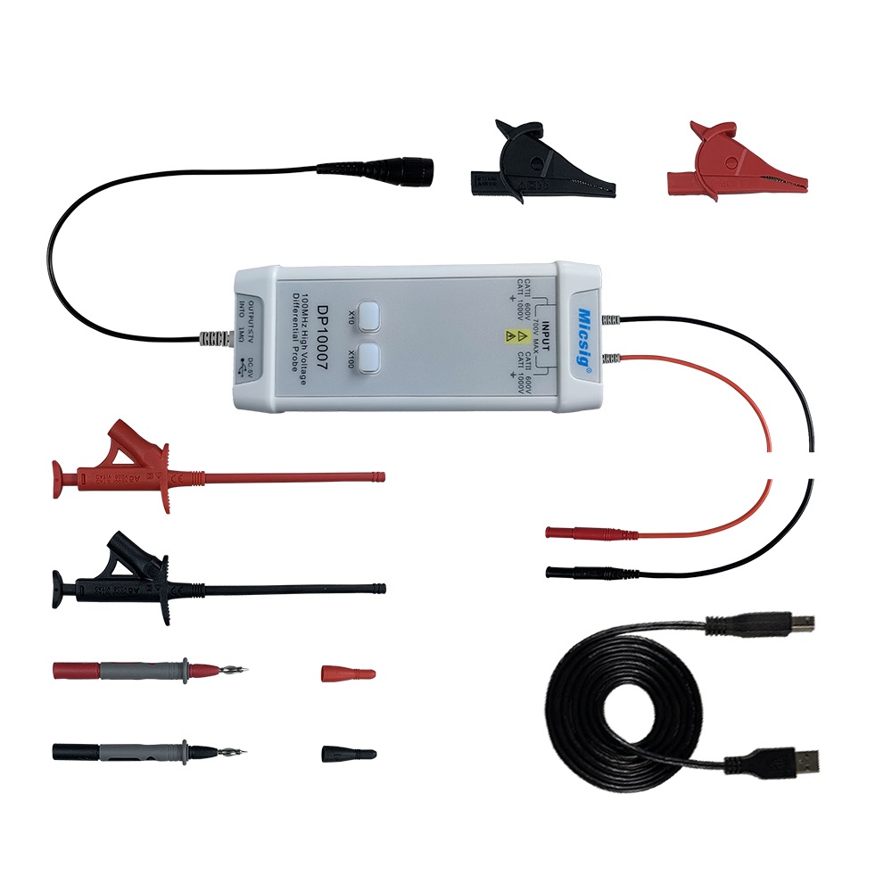
In addition to the actual differential probe, the case contains:
- Two heavy-duty measuring pins with a sharp point with a length of 12 cm.
- Two even heavier duty crocodile clips.
- Two sturdy, but very flexible measuring hooks with a length of 19 cm.
- A USB-B to USB-A cable with a length of 100 cm.
- The manual in English.
As the picture below shows, this all leaves a very solid first impression. The well-known expression 'cheap Chinese junk' is absolutely not applicable here! All attributes are designed to prevent accidental touching of live parts. Contact pins are completely hidden in insulating parts and only make contact with each other once these insulating parts have been pushed together.
 |
| The DP10007 and its attributes. (© 2022 Jos Verstraten) |
The DP10007 differential probe itself
The probe itself is contained in a sturdy plastic case measuring 14.5 cm x 6.0 cm x 2.3 cm. The two measurement leads come out of the right side of the casing. These are 40 cm long and made of very flexible copper wire that is insulated with a thick silicon cover. From the left side comes the output cable with a length of 85 cm that you have to connect to your oscilloscope via a fully insulated BNC connector. Next to this cable is the USB-B connector for connecting the USB power supply. The three cables are equipped with strong anti kink protections.
In the long side there is another USB-A connector. In the manual, this is indicated as 'Power Output'. What the purpose of this connector is, however, is not explained.
On the front of the housing are two illuminated push buttons. These allow you to set the attenuation of the probe to ten or one hundred. The button of the chosen range will of course light up. If this LED starts flashing, the probe is overloaded. That is, the differential voltage between the two input leads is greater than 70 V or 700 V and the output voltage is likely to be distorted.
 |
| The appearance of the DP10007. (© 2022 Jos Verstraten) |
The manual
We have included the four-page manual in our account on Google Drive. You can view it via the link below:
➡ DP10007_Manual.pdf
The technical specifications of the DP10007
The specs of this probe provided by the manufacturer are:
- Bandwidth: 100 MHz
- Rise time: 3.5 ns
- Attenuation: 10x, 100x
- Attenuation accuracy: ±2 %
- Maximum differential voltage inputs, 10x position: 70 V
- Maximum differential voltage inputs, position 100x: 700 V
- Maximum noise voltage 10x: less than 15 mVrms
- Maximum noise voltage 100x: less than 60 mVrms
- Common Mode Rejection Factor at 50 Hz: -80 dB
- Common Mode Rejection Factor at 20 kHz: -60 dB
- Common Mode Rejection Factor at 1 MHz: -50 dB
- Input impedance between both inputs: 8 MΩ / 1.25 pF
- Input impedance between input and ground: 4 MΩ / 2.5 pF
- Maximum output voltage: ±7.0 V
- Overvoltage alarm: flashing LEDs
- Supply voltage: +5.0 Vdc (USB power supply)
- Power consumption: 1.25 W
The electronics in the DP10007
The two halves of the plastic housing have been carefully welded together and the device's internals can only be admired after thorough dismantling of the probe. This is something that this poor blog cannot afford. Fortunately, one Dave Jones did dismantle a copy of the DP10007 and published the photos on Flickr. We are happy to adopt these photos, in slightly modified form!
The two large tin-covered pads on the far left of the PCB are soldered to the two test leads. You can see that these pads are directly connected to an input attenuator, composed of four resistors connected in series. These are bridged with the necessary frequency-compensating capacitors. In order to match the resistive and capacitive parts of the input attenuator, two trimming capacitors are present on the two inputs.
Thanks to the large slot in the PCB, the 'Creepage and Clearance Distances' are excellent with this design!
The differential amplifier is composed of two THS4631 'High Speed FET-Input Operational Amplifiers' and a THS3091 'Single High-Voltage, Low Distortion, Current-Feedback Operational Amplifier' from Texas Instruments. These circuits ensure the large bandwidth up to 100 MHz. Behind the two THS4631 chips you can see a relay that is used to switch the attenuator between 10x and 100x. With two adjustment potentiometers, the two attenuation factors can be precisely adjusted to 10x and 100x.
The rest of the electronics is necessary for converting the +5 Vdc USB supply into the necessary symmetrical supply voltages for the three op-amps, for the range switching with the push buttons and for the overrange indication.
The input resistance
The differential resistance between both inputs is measured as 8.073 MΩ. The resistances between the ground of the output connector and one of both inputs are 4.036 MΩ and 4.034 MΩ.
The output resistance
This is not specified, but is of course an important parameter. The lower, the better! We measured it in the 10x mode with a 5.00 V, 1 kHz sine wave voltage at the input. Unloaded, we measured 501.12 mV at the output. When we load the output with a resistor of 100 Ω and 1 %, the output voltage drops to 182.20 mV. This means that over the internal resistance of the probe a voltage of 318.92 mV falls. Ohm's law tells us that the output resistance of the DP10007 is 175 Ω.
Power consumption
At a supply voltage of 4.85 V, the supply current is 0.21 A. The power consumption is therefore 1.02 W.
The device's own noise
This characteristic was measured with short-circuited inputs and in both sensitivity positions. The Philips millivoltmeter PM2454 was chosen as measuring instrument:
- Position 10x: 0.28 mV
- Position 100x: 0.05 mV
On the oscilloscope, the following pictures appear. To assess the own noise of the oscilloscope, the input of the second channel (blue trace) was short-circuited and set to the same sensitivity.
The accuracy of attenuation
To test this, a number of voltages are applied to the input. The voltages are first measured with our reference meter ET3255. Afterwards, the output voltage of the DP10007 is measured with the same meter in the two positions of the attenuator (if applicable). The results are summarised in the table below.
The harmonic distortion
A differential probe is also useful if you want to test an audio power amplifier of which none of the speaker outputs is connected to ground. That is for example the case with balance output stages that are often used in power amplifier ICs. You can then use such a probe to convert the voltage between the two speaker outputs to a voltage referenced to ground that you can measure on your oscilloscope. But then the probe must process the output signal of the amplifier without too much harmonic distortion! So we measured the harmonic distortion of the DP10007 at various frequencies with an input voltage of 10 V peak to peak. The input signal (yellow trace) comes from our Philips sine wave generator PM5109S with a distortion of 0.03 %.
At 1 kHz and 100x we measure a total harmonic distortion of 0.24 %. At 10 kHz and position 10x we measure the lowest value, only 0.12 % (blue trace). As the oscillogram below shows, this distortion consists mainly of the second harmonic of the input signal.
How to continue testing?
The DP10007 attenuate the voltage between its two inputs by ten or one hundred times and put this attenuated signal on its output. The shape of the signal should not change at all. So if you put the output of the probe on one channel of your oscilloscope and the input voltage of the probe on the other channel, but with a ten or one hundred times lower sensitivity, then both images should be exactly identical.
Of course, you must then be sure that both channels of your scope have identical properties over the entire measuring range. We have checked this on our XDS2102A from OWON and this device completely meets this requirement.
This allows us to properly assess the DP10007's processing of signals with various frequencies and wave forms.

Processing of a 1 kHz sine wave
As can be seen from the oscillograms below, the output, both in the 10x and 100x position, is an exact copy of the input voltage. The yellow trace shows the output signal, the blue trace the input signal. Both traces are virtually the same, so no attenuation or phase shift. The probe works perfectly!
Processing of a 5 MHz sine wave
At this frequency we notice that the output signal is slightly larger than it should be, look at the oscillograms below where the yellow trace (the output voltage) is slightly larger than the blue trace (the input voltage). But in addition, at this frequency there is already a clearly noticeable phase shift present between the input and the output signal.
Processing a 20 MHz sine wave
At this frequency our function generator UTG9005C-II lets us down and we have to switch to our high frequency generator TF2015. However, this generator delivers a much smaller output voltage, which is why the sensitivity settings of the oscilloscope are suddenly different. What immediately strikes us is that in the 10x position, the output signal (yellow trace) is still larger than the input signal (blue trace), but that in the 100x position, the DP10007 starts to suffer from its bandwidth limitations. In addition, the probe causes an increasing phase shift between its input and output.
Processing a 100 MHz sine wave
Finally, how the DP10007 processes a 100 MHz sine wave. Because our oscilloscope automatically switches to a limited bandwidth at the very highest time base settings and a sensitivity of more than 5 mV/div, we cannot use the sensitivity of 1 mV/div as in the previous measurement. Therefore, the two oscillograms below are somewhat limited in size. But they do give a good insight into how well or poorly the probe performs at this frequency. In both modes, the output signal on the screen is attenuated by a factor of 0.554 compared to the input signal. This corresponds to a signal attenuation of approximately 5 dB. According to the specifications, the bandwidth of the DP10007 is 100 MHz, and if the manufacturer adheres to the international convention that the bandwidth is determined by the frequency at which the signal is attenuated by 3 dB, then our copy does not achieve the promised bandwidth.
Processing a 1 MHz square wave voltage
The DP10007 performs great, just look at the oscillograms below. The output signals are identical to the input signals. This despite the already slightly noticeable signal attenuation at 20 MHz!
The rise time
To check the rise time, we use our pulse generator PM5704, which delivers very steep pulses. We measure the rise time in the 10x mode with a 50 Ω terminator on the input of the oscilloscope. In the oscillogram below, you can see that our oscilloscope measures a rise time of 12.0 ns. The scope itself has a rise time of about 3.5 ns. Also the rise time of the output pulse of the generator is not negligible and is specified as smaller than 9 ns. From this measurement you can see that the specified rise time of 3.5 ns can be achieved in practice.
All our measurements show that this differential probe behaves according to the specifications. We do measure a slightly smaller bandwidth than the specified 100 MHz, but in practice, you will probably never make a measurement with this probe where this becomes a problem. For most practical work, measuring at circuits that are not galvanically separated from the mains and measuring the voltage over a component that is not connected to the ground, this probe will be of excellent service.
Whether you are prepared to pay the not insignificant investment of € 170.00 we cannot judge, that depends entirely on the nature and frequency of such work in your practical situation.

(Banggood sponsor ad)
Micsig DP10007 Oscilloscope High-Voltage Differential Probe
- Bandwidth: 100 MHz
- Rise time: 3.5 ns
- Attenuation: 10x, 100x
- Attenuation accuracy: ±2 %
- Maximum differential voltage inputs, 10x position: 70 V
- Maximum differential voltage inputs, position 100x: 700 V
- Maximum noise voltage 10x: less than 15 mVrms
- Maximum noise voltage 100x: less than 60 mVrms
- Common Mode Rejection Factor at 50 Hz: -80 dB
- Common Mode Rejection Factor at 20 kHz: -60 dB
- Common Mode Rejection Factor at 1 MHz: -50 dB
- Input impedance between both inputs: 8 MΩ / 1.25 pF
- Input impedance between input and ground: 4 MΩ / 2.5 pF
- Maximum output voltage: ±7.0 V
- Overvoltage alarm: flashing LEDs
- Supply voltage: +5.0 Vdc (USB power supply)
- Power consumption: 1.25 W
The electronics in the DP10007
The two halves of the plastic housing have been carefully welded together and the device's internals can only be admired after thorough dismantling of the probe. This is something that this poor blog cannot afford. Fortunately, one Dave Jones did dismantle a copy of the DP10007 and published the photos on Flickr. We are happy to adopt these photos, in slightly modified form!
The two large tin-covered pads on the far left of the PCB are soldered to the two test leads. You can see that these pads are directly connected to an input attenuator, composed of four resistors connected in series. These are bridged with the necessary frequency-compensating capacitors. In order to match the resistive and capacitive parts of the input attenuator, two trimming capacitors are present on the two inputs.
Thanks to the large slot in the PCB, the 'Creepage and Clearance Distances' are excellent with this design!
The differential amplifier is composed of two THS4631 'High Speed FET-Input Operational Amplifiers' and a THS3091 'Single High-Voltage, Low Distortion, Current-Feedback Operational Amplifier' from Texas Instruments. These circuits ensure the large bandwidth up to 100 MHz. Behind the two THS4631 chips you can see a relay that is used to switch the attenuator between 10x and 100x. With two adjustment potentiometers, the two attenuation factors can be precisely adjusted to 10x and 100x.
The rest of the electronics is necessary for converting the +5 Vdc USB supply into the necessary symmetrical supply voltages for the three op-amps, for the range switching with the push buttons and for the overrange indication.
 |
| The two sides of the PCB of the DP10007. (© 2021 Dave Jones, edited by Jos Verstraten) |
The DP10007 of Micsig tested
The input resistance
The differential resistance between both inputs is measured as 8.073 MΩ. The resistances between the ground of the output connector and one of both inputs are 4.036 MΩ and 4.034 MΩ.
The output resistance
This is not specified, but is of course an important parameter. The lower, the better! We measured it in the 10x mode with a 5.00 V, 1 kHz sine wave voltage at the input. Unloaded, we measured 501.12 mV at the output. When we load the output with a resistor of 100 Ω and 1 %, the output voltage drops to 182.20 mV. This means that over the internal resistance of the probe a voltage of 318.92 mV falls. Ohm's law tells us that the output resistance of the DP10007 is 175 Ω.
Power consumption
At a supply voltage of 4.85 V, the supply current is 0.21 A. The power consumption is therefore 1.02 W.
The device's own noise
This characteristic was measured with short-circuited inputs and in both sensitivity positions. The Philips millivoltmeter PM2454 was chosen as measuring instrument:
- Position 10x: 0.28 mV
- Position 100x: 0.05 mV
On the oscilloscope, the following pictures appear. To assess the own noise of the oscilloscope, the input of the second channel (blue trace) was short-circuited and set to the same sensitivity.
.") |
The DP10007's own noise (yellow trace). (© 2022 Jos Verstraten) |
The accuracy of attenuation
To test this, a number of voltages are applied to the input. The voltages are first measured with our reference meter ET3255. Afterwards, the output voltage of the DP10007 is measured with the same meter in the two positions of the attenuator (if applicable). The results are summarised in the table below.
 |
| The accuracy of attenuation. (© 2022 Jos Verstraten) |
The harmonic distortion
A differential probe is also useful if you want to test an audio power amplifier of which none of the speaker outputs is connected to ground. That is for example the case with balance output stages that are often used in power amplifier ICs. You can then use such a probe to convert the voltage between the two speaker outputs to a voltage referenced to ground that you can measure on your oscilloscope. But then the probe must process the output signal of the amplifier without too much harmonic distortion! So we measured the harmonic distortion of the DP10007 at various frequencies with an input voltage of 10 V peak to peak. The input signal (yellow trace) comes from our Philips sine wave generator PM5109S with a distortion of 0.03 %.
At 1 kHz and 100x we measure a total harmonic distortion of 0.24 %. At 10 kHz and position 10x we measure the lowest value, only 0.12 % (blue trace). As the oscillogram below shows, this distortion consists mainly of the second harmonic of the input signal.
 |
| Measurement of the harmonic distortion at 10 kHz. (© 2022 Jos Verstraten) |
How to continue testing?
The DP10007 attenuate the voltage between its two inputs by ten or one hundred times and put this attenuated signal on its output. The shape of the signal should not change at all. So if you put the output of the probe on one channel of your oscilloscope and the input voltage of the probe on the other channel, but with a ten or one hundred times lower sensitivity, then both images should be exactly identical.
Of course, you must then be sure that both channels of your scope have identical properties over the entire measuring range. We have checked this on our XDS2102A from OWON and this device completely meets this requirement.
This allows us to properly assess the DP10007's processing of signals with various frequencies and wave forms.
Processing of a 1 kHz sine wave
As can be seen from the oscillograms below, the output, both in the 10x and 100x position, is an exact copy of the input voltage. The yellow trace shows the output signal, the blue trace the input signal. Both traces are virtually the same, so no attenuation or phase shift. The probe works perfectly!
 |
| Processing of a 1 kHz sine wave. (© 2022 Jos Verstraten) |
Processing of a 5 MHz sine wave
At this frequency we notice that the output signal is slightly larger than it should be, look at the oscillograms below where the yellow trace (the output voltage) is slightly larger than the blue trace (the input voltage). But in addition, at this frequency there is already a clearly noticeable phase shift present between the input and the output signal.
 |
| Processing of a 5 MHz sine wave. (© 2022 Jos Verstraten) |
Processing a 20 MHz sine wave
At this frequency our function generator UTG9005C-II lets us down and we have to switch to our high frequency generator TF2015. However, this generator delivers a much smaller output voltage, which is why the sensitivity settings of the oscilloscope are suddenly different. What immediately strikes us is that in the 10x position, the output signal (yellow trace) is still larger than the input signal (blue trace), but that in the 100x position, the DP10007 starts to suffer from its bandwidth limitations. In addition, the probe causes an increasing phase shift between its input and output.
 |
| Processing of a 20 MHz sine wave. (© 2022 Jos Verstraten) |
Processing a 100 MHz sine wave
Finally, how the DP10007 processes a 100 MHz sine wave. Because our oscilloscope automatically switches to a limited bandwidth at the very highest time base settings and a sensitivity of more than 5 mV/div, we cannot use the sensitivity of 1 mV/div as in the previous measurement. Therefore, the two oscillograms below are somewhat limited in size. But they do give a good insight into how well or poorly the probe performs at this frequency. In both modes, the output signal on the screen is attenuated by a factor of 0.554 compared to the input signal. This corresponds to a signal attenuation of approximately 5 dB. According to the specifications, the bandwidth of the DP10007 is 100 MHz, and if the manufacturer adheres to the international convention that the bandwidth is determined by the frequency at which the signal is attenuated by 3 dB, then our copy does not achieve the promised bandwidth.
 |
| Processing of a 100 MHz sine wave. (© 2022 Jos Verstraten) |
Processing a 1 MHz square wave voltage
The DP10007 performs great, just look at the oscillograms below. The output signals are identical to the input signals. This despite the already slightly noticeable signal attenuation at 20 MHz!
 |
| Processing of a 1 MHz block voltage. (© 2022 Jos Verstraten) |
The rise time
To check the rise time, we use our pulse generator PM5704, which delivers very steep pulses. We measure the rise time in the 10x mode with a 50 Ω terminator on the input of the oscilloscope. In the oscillogram below, you can see that our oscilloscope measures a rise time of 12.0 ns. The scope itself has a rise time of about 3.5 ns. Also the rise time of the output pulse of the generator is not negligible and is specified as smaller than 9 ns. From this measurement you can see that the specified rise time of 3.5 ns can be achieved in practice.
 |
| Measurement of the rise time of the DP10007. (© 2022 Jos Verstraten) |
Our opinion of the DP10007 from Micsig
All our measurements show that this differential probe behaves according to the specifications. We do measure a slightly smaller bandwidth than the specified 100 MHz, but in practice, you will probably never make a measurement with this probe where this becomes a problem. For most practical work, measuring at circuits that are not galvanically separated from the mains and measuring the voltage over a component that is not connected to the ground, this probe will be of excellent service.
Whether you are prepared to pay the not insignificant investment of € 170.00 we cannot judge, that depends entirely on the nature and frequency of such work in your practical situation.
Micsig DP10007 Oscilloscope High-Voltage Differential Probe