|
With three modules, which together cost less than € 45.00, you can create a small but very professional laboratory power supply that provides you with a voltage of up to 32.00 Vdc and a current of up to 2.000 A. Of course, the device works as a constant voltage and current source. |
What you get for your money
Introduction to this laboratory power supply
To get you excited about this project we start this article with a picture of how it will look like. For a total of € 45.00 you will receive a very small laboratory power supply that will be a gem in your electronics workshop:
- Dimensions: 13.0 cm x 11.8 cm x 4.2 cm
- Housing: anthracite anodized aluminum
- Mode: constant voltage or constant current
- Constant output voltage: 0.00 Vdc to 32.00 Vdc
- Voltage setting resolution: 10 mV
- Constant output current: 0.000 mA to 2.000 A
- Current setting resolution: 1 mA
- Maximum power output setting: 0.00 W to 96.00 W
- Display: voltage, current, power
- Memory: ten data sets
- Presets: five settings per data set
- Quick selection of one of the ten data sets
- Cooling with built-in fan
 |
| The final result of your work. Isn't it a beauty? (© 2018 Jos Verstraten) |
If you spend some time behind your PC, you can compile the following shopping list for the prices listed:
- 1 x YU3602 power adapter 36 V - 2 A from Shenzhen Boxinqi Technology, approximately € 9.00.
- 1 x DPS3003 32V - 3A buck step-down module from Ruideng, about € 20.00.
- 1 x Housing for DPS3003 from Ruideng, about € 16.00.
The YU3602 power adapter 36 V - 2 A
The presentation
This power adapter is actually intended to power laptops but is extremely useful for this project. Although the DPS3003 can withstand an input voltage of 40 V and can supply 3 A, we could not find a cheap power adapter with this output current. With the 2 A output current of this adapter you have more than enough power in practice.
 |
| The power adapter YU3602 provides the necessary DC voltage for the DPS3003. (© Aliexpress) |
This AC adapter has the following specifications:
- Input voltage: 100 Vac to 240 Vac
- Output voltage: 36 Vdc
- Output current: 2 A
- Output power: 96 W
- Output connector: 5.5 mm x 2.1 mm
- Input connector: Euro plug
- Dimensions: 12.8 cm x 5.5 cm x 3.4 cm
- Weight: 350 g
The electronics
The YU3602 obviously uses switched techniques and looks very neat internally. The only annoying thing for our application is that the output cable has a 5.5 mm x 2.1 mm connector. However, the housing of the DPS3003 assumes a power connection via two 4 mm banana plugs. So you have two options:
- Cut off the 5.5 mm x 2.1 mm connector from the cable, free up the two wires and provide two banana plugs.
- Look for a chassis terminal for a 5.5 mm x 2.1 mm connector and attach it to the back of the housing. That is of course the best option, but it is not easy to find a good quality chassis terminal. We found a sturdy metal version at Banggood for € 1.57 under order number 1188681.
 |
| A look into the internal of the YU3602. (© 2018 Jos Verstraten) |
The better the voltage that goes into a power supply, the better the voltage that comes out of it. So it is interesting to measure how good the stabilization of the YU3602 is. As the graph below shows, that's not that bad! The voltage drops from 36.35 Vdc to 36.18 Vdc between no-load and a load current of 2 A. That corresponds to an internal resistance of 0.105 Ω.
 |
| The output voltage of the YU3602 in function of the load current. (© 2018 Jos Verstraten) |
The DPS3003 module
What is the DPS3003?
The DPS3003 is a so called 'synchronous buck step down' module. With this principle you can derive a lower DC voltage from a high DC voltage and that with an enormously high efficiency. This means that very little power is lost in the circuit itself and therefore minimal cooling is required. The principle is shown in the figure below. The input voltage Uin goes via an electronic switch S1 to a coil L1 and a capacitor C1. Over the capacitor the desired lower output voltage Uuit is created. When you close the switch S1, a linearly increasing current flows through the series connection of L1 and C1. A characteristic of coils is that they resist a current variation by generating a voltage that counteracts the current variation. This voltage UL is connected in series with the output voltage Uuit. However, the sum is equal to the input voltage Uin. It will be clear that the output voltage is equal to the input voltage minus the voltage across the coil. When the output voltage is equal to the set point value, the switch S1 is opened. There will be no current flowing from the input voltage. However, magnetic energy has built up in the coil and this will cause a second current to flow through the coil, which flows via the diode D1. The voltage UL remains on the coil, so that the voltage across the capacitor remains constant. By opening and closing the switch very quickly and by varying the times of opening and closing, you can generate a nice and adjustable DC voltage over the capacitor with a minimum ripple.
 |
| The principle of a synchronous buck step down circuit. (© 2018 Jos Verstraten) |
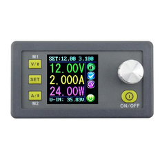
The complete electronics of the DPS3003 are housed in a small box of only 79 mm x 43 mm x 41 mm. Dominating the front panel is a display with dimensions 28 mm x 28 mm. In that display you can see a lot of data:
- The current output voltage (green).
- The current output current (yellow).
- The current output power (purple).
- The set values of voltage and short-circuit current (light blue).
- The actual value of the input voltage (light blue).
- A number of pictograms representing the function of the module.
On the left you see three minuscule push buttons, with which you set the voltage and current and configure the ten memory locations. On the right is a rotary encoder, which allows you to quickly set the value of the output variables by turning on and clicking on them. Under the encoder there is a fourth push button, with which you can switch the voltage to the output terminals.
 |
| The DPS3003 module from three perspectives. (© Banggood) |
- Input voltage (max): 40.00 Vdc
- Output voltage: 0.00 Vdc to 32.00 Vdc
- Output current: 0.000 mA to 3.000 mA
- Output power range: 0 W to 96 W
- Output voltage resolution: 10 mV
- Output current resolution: 1 mA
- Output power resolution: 10 mW
- Output voltage accuracy: 0.5 % ±1 digit
- Output current accuracy: 0.5 % ±2 digits
- Dimensions: 79 mm x 43 mm x 41 mm
- Weight: 65 g
The enclosure for the DPS3003
An excellent quality building kit
The enclosure you need to build around the DPS3003 is supplied as a kit and is of truly outstanding quality. This package includes a small pre-assembled PCB. The only purpose of this PCB is to reduce the input voltage of the power supply to 12 Vdc for the miniature fan.
 |
| The parts of the enclosure. (© 2018 Jos Verstraten) |
The construction of the laboratory power supply
Assembling the back panel
If you have chosen to supply the voltage of the YU3602 power adapter via the 5.5 mm x 2.1 mm connector, you must first drill a hole in the rear panel for the 5.5 mm chassis terminal. Do this next to the two holes for the 4 mm terminals. After mounting, solder two solid wires to the lugs of this connector and bend these lugs as flat as possible.
Mount on the rear panel the power switch, two 4 mm connectors and the fan. The two wires of the 5.5 mm connector are attached under the nuts with which you screw the two 4 mm connectors. Note the plus and minus!

The PCB should then be screwed to the two 4 mm connectors with the second set of nuts. Make sure that the bottom side of the PCB does not make contact with the connection lugs of the 5.5 mm connector. Afterwards you can solder the two wires of the switch and the two wires of the fan on the PCB. In the two large holes in the upper left corner of the PCB, solder two solid wires to the input connector of the DPS3003 module.
 |
| The assembly of the back panel. (© Banggood) |
The rest is a piece of cake. You attach the two remaining 4 mm connectors in the front panel and click the DPS3003 module into the large hole. Note the position of the module! Solder two wires to the 4 mm connectors and screw them into the OUT- and OUT+ terminal blocks of the module. Screw the two wires that are coming from the rear PCB into the IN- and IN+ terminal blocks of the module. Attach the front and back panels to the lower half of the case. That is the part with the openings for air circulation. Make sure these openings are under the module. Snap the upper half of the case into the lower half and attach this part to the front and back panels.
 |
| Final assembly of the laboratory power supply. (© Banggood) |
Operating your laboratory power supply
Introduction to the system
To learn to use the power supply, we will set the output voltage to 5.00 V and the current limitation to 1.000 A. Connect the YU3602 power adapter to the 230 V power supply and plug the output plug into the connector on the back of the power supply. Close the switch on the back of the enclosure. If everything has gone well so far, you will hear that the fan is going to run (quite a noisy type!) and you will see the manufacturer's logo on the display. A little later the display will become active and you will see that the three parameters voltage, current and power are set to zero. The bottom line of the display shows the value of the input voltage in light blue. This should of course be approximately 36.00 V.
Setting the output voltage to 5.00 V
Press and release the upper button marked 'V/↑'. On the top line of the display you will see a number lights up purple. This is the last digit of the voltage setting (00,0XV) which you can now set to the desired value by turning the encoder knob. Set this to '0' and click on the button. You will now see the number on the left next to it becoming purple (00,X0V). Set this also to '0' and click on the encoder again. The next two left digits (XX,00V) will become purple, set it to '05'. Finally click on the 'V/↑' button again.
Setting the current limit to 1,000 A
Press and release the lower button marked 'A/↓'. You will now see the number of the mA setting (0.00XA) changes to purple. As explained, you can adjust the current limit to 1.000 A.
The voltage to the output
Finally, press the 'ON/OFF' button under the encoder. The display immediately takes the values '05.00V' and '0.000A' and the configured voltage of 5.00 V appears on the two output connectors of the power supply. Briefly short circuit the power supply with a wire. The display responds immediately with '1,000A'. The output voltage and output power displays will of course indicate something, because the internal wiring and the short circuit wire have a certain resistance so the voltage will not go all the way to zero.
Remark
The voltage and current settings you made are stored in the memory as data set M0. When you turn the unit on again, both values go to the last set values and you can connect them to the output connectors with one press of the 'ON/OFF' button.
The information in the display
The display provides more information than the selected voltage and current and power. All functions shown in the display are summarized in the below illustration.
 |
| The meaning of the symbols in the display. (© 2018 Jos Verstraten) |
Press the middle 'SET' button briefly and the display changes drastically, as shown in the figure below. In this screen you can configure the ten data-sets in the memory one by one. You will see the data of data set M0, of which you have already set a few parameters:
U-SET: 05.00V
I-SET: 1.000A
You can scroll through the seven parameters by pressing the two arrow keys:
- S-OVP:
Set Over Voltage Protection. You can set a limiting voltage as described above. After entering the numerical value with the rotary encoder, briefly press 'SET' again to set the value. If, for any reason, the voltage between the terminals of the power supply exceeds this value, the power supply immediately switches off. - S-OCP:
Set Over Current Protection. The same story, but for the supplied current. - S-OPP:
Set Over Power Protection. The same, but for the power supplied. - B-LED:
Adjusts the display brightness between 0 and 5. - M-PRE:
Choice of data set.
 |
| The menu for configuring the parameters of a data set. (© 2018 Jos Verstraten) |
For safety reasons, press the 'ON/OFF' button so that the output terminals are disconnected from the circuit and the output goes to 0.00 V. From the main menu, briefly press the 'SET' button. Use the arrow buttons to go to the 'M-PRE' option, press the encoder briefly. Turn the encoder until the number of the data set in which you want to store the presets appears on the display. Press the encoder button again. Turn the encoder until the 'ON' option appears. Press and release the 'SET' button. You can now use the arrow keys to select a parameter and set its value with the encoder as described. Do not forget to press the 'SET' button after setting!
Ready? Then go back to 'M-PRE', select the data set and press 'SET' for two seconds. The number of the data set appears on the right of the display to indicate that the data has been stored. Finally, press and release the 'SET' button. You will return to the main menu of the device.
Selecting one of the data sets
The data set M0 is the default set. If you select one of the other sets, the settings of this group are automatically transferred to the set M0. To select a data set, press the 'SET' button for more than two seconds. Turn the encoder until the number of the desired data set appears in the display. Finally, briefly press the 'SET' button. The settings of the data set are taken over by M0 and become active.
Quick selection of data set M1 and M2
Save the settings you use most often, for example 5.00 V and 12.00 V, in the M1 and M2 data sets. You can call them up very quickly by pressing the 'V/↑' (M1) or 'A/↓' (M2) keys for more than two seconds.
The performance of your laboratory supply
Output voltage stability
This power supply behaves perfectly. Our first test was to set the output voltage to 5.00 V and gradually load the power supply to 2.000 A. The output voltage decreased from 5.00 V to 4.97 V. The measurements were repeated with an output voltage of 12.00 V at no-load. At 2.000 A, the output voltage decreased to 11.98 V. Finally measured at an output voltage of 30.00 V. At 2.000 A, the power supply delivered 29.99 V.
Accuracy of the display
Here too, the DPS3003 delivers optimum performance. The measurements of voltage and current on the display were compared with those on a good multimeter. The largest deviations we found were only 10 mV and 3 mA.
Noise and ripple on the output voltage
Switched power supplies are known to contaminate their output voltage with residues of the high-frequency signal with which the synchronous buck step down circuitry works. The DPS3003 is unfortunately no exception. The screenshot below shows the residual signal at the output voltage, which is virtually independent of the load current in terms of size. Glitches of 200 mV at an output voltage of 12 Vdc are of course very large. Fortunately, the frequency of these glitches is quite high, in fact 135 kHz. You can easily filter out this residue at the circuit to be supplied by inserting a 100 nF capacitor between the power connections. By the way, you always have to do this, even with power supplied by a linear power supply!
 |
| The switching residues at the output voltage of 12.00 V at 2,000 A load. (© 2018 Jos Verstraten) |
We had the power supply run for hours at an output voltage of 5.00 V and a load current of 2.000 A. The metal housing did not noticeably heat up and the air blown out by the fan was not warmer than the ambient air.
Our opinion on the DSP3003
We are extremely satisfied with this power supply. You obtain a semi-professional power supply that leaves nothing to be desired for an exceptionally low price. The assembly of the various parts and modules should not be a problem for an experienced electronics hobbyist.

DPS3003 32 V-3 A Buck Adjustable Voltage Power Supply