Introducing Miniware's DS212 oscilloscope
The DS212 'smartphone' oscilloscope
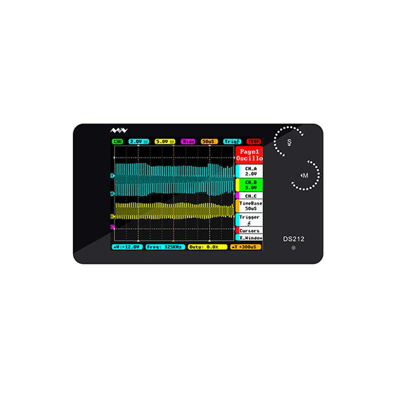
The DS212 was developed by e-Design and is sold under the brand name Miniware. The oscilloscope is housed in a beautiful black aluminium case of only 100 mm by 56.5 mm by 10 mm and therefore looks rather like a small smartphone. The display measures 58 mm by 42 mm and has a resolution of 320 by 240 pixels. As you can see from the picture below, there is a lot of data on this small screen, but fortunately, you can delete a lot of unnecessary data with a few clicks of the buttons.
On the left side there are three MCX connectors, two for the two inputs and one for the output of the function generator. Indeed, the DS212 also has a primitive function generator on board. On the right side, you will find a micro-USB connector for charging the internal battery and downloading the screen shots stored in the memory to your PC.
On the top you will notice two buttons. The left one is the 'RUN/PAUSE'-button with which you can also quickly save a picture of the screen in the internal memory. The right one switches the device on or off.
You control the oscilloscope by turning and clicking two small thumbwheel encoders 'S' and 'M' in the top right corner of the device.
Below the notation DS212 is a red LED that lights up while the battery is being charged and goes out when the battery is fully charged.
 |
| Miniware's mini oscilloscope DS212. (© Banggood) |
The Protective Rubber Case
You can also order a protective rubber case for the DS212. This costs about € 10.50 and contains, besides the rubber case, also a very handy backrest. The backrest can be glued to the back of the DS212. By adjusting this support to a certain position, you can place the device at an easily readable angle on your work table.
 |
| The optional rubber protective cover with handy backrest. (© AliExpress) |
The delivery of the package
Both the oscilloscope and the protective case are packed in sturdy cardboard boxes, so even if your Chinese supplier ships both boxes sloppily in a piece of black plastic, there is hardly any chance of shipping damage.
 |
The packaging of the oscilloscope and protective case. |
The extra components supplied
In the package of the oscilloscope, there are two plastic boxes. One contains the DS212 itself, the other the connecting cables. These are nicely packed in the box below:
- Two 1/1 and 1/10 measuring probes with a length of 115 cm
- One micro-USB to USB-A cable with a length of 35 cm
- Two ground wires with a length of 15 cm
- A very small hex key to unscrew the housing so that you can replace the battery if necessary.
 |
| The probes and cables are neatly packed. (© 2021 Jos Verstraten) |
The manual
In the package of the oscilloscope is a well-designed 44 page booklet in which the operation of the DS212 is explained very comprehensively and clearly in English and Chinese. Well done! A lot of electronic equipment manufacturers can take this manual as an example. We have filtered out the English part and put it on our account on Google Drive:
➡ DS212_Manual.pdf
The specifications
According to the manufacturer, the DS212 has the following specifications:
- Channels: two analogue channels 'CH_A' and 'CH_B'
- Analogue bandwidth: 1 MHz
- Sensitivity: 20 mV/div ~ 10 V/div (1-2-5 steps)
- Input impedance: 1 MΩ
- Input voltage with 1/1 probe: ±40 V max.
- Coupling: DC/AC
- Sampling rate: 10 MSa/s max.
- Sample memory depth: 8 kB
- Time base: 1 μs/div ~ 2 s/div (1-2-5 steps)
- Trigger mode: rising or falling edge
- Sync mode: automatic, normal, single, none, average
- Mathematical channel 'CH_C': -A, -B, A+B, A-B, RecA, RecB, RecC
- Analogue measurements: five measurement values of the input signals
- Function generator: sine ~ rectangle ~ triangle ~ sawtooth
- Frequency range sine ~ triangle ~ saw tooth: 10 Hz ~ 10 kHz (1-2-5 steps)
- Frequency range rectangle: 10 Hz ~ 1 MHz (1-2-5 steps)
- Output voltage sine: 675 mVrms constant
- Rectangle output voltage: 3.0 Vpeak-to-peak constant
- Duty cycle rectangle: 10 % ~ 90 %
- Storage: 8 MB flash memory
- Microprocessor: STM32F303VC
- ADC: Internal to the processor
- USB port: micro-USB
- Login to Windows: as an external hard drive with name 'DS212'
- Battery: 500 mAh
- Display: TFT-LCD, 2.8", 320 x 240 pixels
- Dimensions: 100 x 56.5 x 10.7 mm
- Weight: 90g
Removing the back panel of the housing
With the supplied hex key you can remove four very small bolts on the back panel. You will then gain access to the circuit board with a large cut-out for the battery. On this side of the PCB you will notice two HC4053 3 x 2-channel analogue multiplexers that are obviously used in the input circuits for range adjustment and AC/DC coupling. Four capacitor trimmers provide capacitive compensation for the voltage dividers.
The other side of the PCB
The PCB is fixed to the housing with three small bolts that can be unscrewed with the same hex key. Think carefully before you do this! It turns out that it takes a lot of effort to get the two thumbwheel encoder discs back between the housing and the PCB in the only correct way.
We did it for you and you can see the result in the photo below. The flatcable goes to the display, of course. In the upper right corner you can see the two encoders that are driven by the two thumbwheels that stick out of the housing by only a few millimetres, but are still easy to turn and press.
The screen with all data
In the figure below, we have presented the screen filled with the maximum amount of data you can make visible.
The top horizontal bar contains data about the selected parameters:
- Status of the battery
- Sensitivity channel 'CH_A'
- Sensitivity channel 'CH_B'
- Function of the 'mathematical' channel 'CH_C'.
- Time base setting
- Trigger setting
- Sync setting
In the package of the oscilloscope is a well-designed 44 page booklet in which the operation of the DS212 is explained very comprehensively and clearly in English and Chinese. Well done! A lot of electronic equipment manufacturers can take this manual as an example. We have filtered out the English part and put it on our account on Google Drive:
➡ DS212_Manual.pdf
The specifications
According to the manufacturer, the DS212 has the following specifications:
- Channels: two analogue channels 'CH_A' and 'CH_B'
- Analogue bandwidth: 1 MHz
- Sensitivity: 20 mV/div ~ 10 V/div (1-2-5 steps)
- Input impedance: 1 MΩ
- Input voltage with 1/1 probe: ±40 V max.
- Coupling: DC/AC
- Sampling rate: 10 MSa/s max.
- Sample memory depth: 8 kB
- Time base: 1 μs/div ~ 2 s/div (1-2-5 steps)
- Trigger mode: rising or falling edge
- Sync mode: automatic, normal, single, none, average
- Mathematical channel 'CH_C': -A, -B, A+B, A-B, RecA, RecB, RecC
- Analogue measurements: five measurement values of the input signals
- Function generator: sine ~ rectangle ~ triangle ~ sawtooth
- Frequency range sine ~ triangle ~ saw tooth: 10 Hz ~ 10 kHz (1-2-5 steps)
- Frequency range rectangle: 10 Hz ~ 1 MHz (1-2-5 steps)
- Output voltage sine: 675 mVrms constant
- Rectangle output voltage: 3.0 Vpeak-to-peak constant
- Duty cycle rectangle: 10 % ~ 90 %
- Storage: 8 MB flash memory
- Microprocessor: STM32F303VC
- ADC: Internal to the processor
- USB port: micro-USB
- Login to Windows: as an external hard drive with name 'DS212'
- Battery: 500 mAh
- Display: TFT-LCD, 2.8", 320 x 240 pixels
- Dimensions: 100 x 56.5 x 10.7 mm
- Weight: 90g
The electronics in DS212
Removing the back panel of the housing
With the supplied hex key you can remove four very small bolts on the back panel. You will then gain access to the circuit board with a large cut-out for the battery. On this side of the PCB you will notice two HC4053 3 x 2-channel analogue multiplexers that are obviously used in the input circuits for range adjustment and AC/DC coupling. Four capacitor trimmers provide capacitive compensation for the voltage dividers.
 |
| The complete electronics are on one PCB. (© 2021 Jos Verstraten) |
The other side of the PCB
The PCB is fixed to the housing with three small bolts that can be unscrewed with the same hex key. Think carefully before you do this! It turns out that it takes a lot of effort to get the two thumbwheel encoder discs back between the housing and the PCB in the only correct way.
We did it for you and you can see the result in the photo below. The flatcable goes to the display, of course. In the upper right corner you can see the two encoders that are driven by the two thumbwheels that stick out of the housing by only a few millimetres, but are still easy to turn and press.
 |
| The microcontroller side of the PCB. (© 2021 Jos Verstraten) |
Working with Miniware's DS212
The screen with all data
In the figure below, we have presented the screen filled with the maximum amount of data you can make visible.
The top horizontal bar contains data about the selected parameters:
- Status of the battery
- Sensitivity channel 'CH_A'
- Sensitivity channel 'CH_B'
- Function of the 'mathematical' channel 'CH_C'.
- Time base setting
- Trigger setting
- Sync setting

The lower horizontal bar shows four measurement data of the input signals:
- Voltage difference between the two vertical cursors
- Measuring function you set in 'Page 2' selection 1
- Measuring function you set in 'Page 2' selection 2
- Time difference between the two horizontal cursors
One of the three 'Pages' is shown on the right of the screen.
On the left you can see a number of coloured triangles representing the 0 V references of the three channels 'CH_A', 'CH_B' and 'CH_C' and the trigger level 'T'.
Finally, you will see two horizontal and two vertical dotted lines with small white triangles. These are, of course, the four cursors you can use to calculate voltage and time differences.
 |
| All the data that can appear on the screen. (© Miniware) |
Three main menus
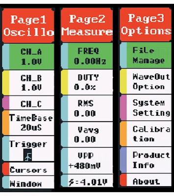
All the functions you can call up are divided into three menus, called 'Pages', which appear on the right of the screen and which you can select by briefly pressing the 'S' button. In the figure below, we have presented these three 'Pages' side by side. In practice, however, only one of the three 'Pages' always appears on the right-hand side of the display.
- 'Page 1: Oscillo'
In this menu you can select all basic functions of the oscilloscope, such as the settings of both inputs, the time base, the triggering, the cursors and the third math channel. - 'Page 2: Measure'
In this menu, you can select from five measurement data of the input signals that you want to see on screen. - 'Page 3: Options'
This 'Page' allows you to configure less frequently used features of the device, such as the file manager for scrolling through stored images, system settings, zero point calibration and the function generator output signal.
 |
| You select one of these three 'Pages' by pressing the 'S' button. (© 2021 Jos Verstraten) |
Selecting and setting a menu option
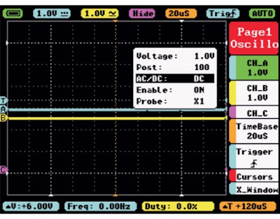
You select one of the options in the menus by turning knob 'M'. The selected option turns green and becomes active by pressing button 'M'. A small window will appear on the screen in which you can set the parameters for this option. As an example, we demonstrate the setting of channel 'CH_A' in the figure below. The option 'CH_A' in 'Page1' is green and you have pressed button 'M'. You see in the window that you can set five parameters:
- Voltage: the sensitivity in V/div
- Post: the horizontal position of the zero volt reference
- AC/DC: the coupling of the input signal
- Enable: enable or disable the channel
- Probe: position of the attenuator on the probe
You select these by turning knob 'M', then set the desired value by turning knob 'S'. Pressing this button confirms your selection. All set? Then press button 'M' again and the window will disappear from the screen.
 |
Selecting the settings of channel 'CH_A'. (© Miniware) |
Deleting the 'Pages' window
Have you set all the options? And you don't need any additional numeric measurement data on the screen? Then the 'Pages' window is superfluous. Switch it off by pressing button 'S' for more than one second. The oscilloscope screen suddenly becomes much wider.
Quickly setting sensitivity and time base
When you have removed the 'Pages' window, you can still quickly change the sensitivity and time base. You can vary the time base by turning the 'S' knob. The sensitivity of the two channels can be varied by turning knob 'M'. Switching from channel 'CH_A' to channel 'CH_B' is done by briefly pressing this button.
Saving a picture of the screen
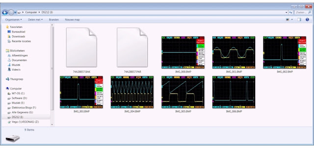
If you press the 'RUN/PAUSE' button for more than one second, DS212 takes a picture of the current screen and saves it as a .BMP file in the internal memory. These pictures have a resolution of 320 by 240 pixels and are easy to export. When you connect the oscilloscope to a USB port of a Windows PC using the USB cable provided, the DS212 is automatically recognized as an external drive 'DS212' and its contents are displayed in a Windows Explorer window. Photo size is about 40 kB and memory size is 8 MB. So, there is space for about 200 photos.
 |
The internal memory in Windows Explorer. (© 2021 Jos Verstraten) |
The third channel 'Ch_C'
This third channel is standard on most digital oscilloscopes and is called the 'mathematical' channel. 'Mathematical' because you can use this channel to display mathematical operations performed on the two channels 'CH_A' and 'CH_B'. This result is shown in purple. Whether this option is really useful remains to be seen, but it is there and so we will discuss it briefly. The DS212 allows you to perform the following operations on both input signals:
- [-A]: the signal at the input 'CH_A' is inverted.
- [-B]: same for the signal at the input 'CH_B'.
- [A+B]: both signals are added together
- [A-B]: input B is subtracted from input A
- [RecA]: the last oscillogram saved in 'CH_A' is displayed on 'CH_C'
- [RecB]: The last oscillogram saved in 'CH_B' is shown on 'CH_C'
- [RecC]: The last oscillogram saved in 'CH_C' is shown on 'CH_C'
The example below shows how the two input signals are added together.
 |
| Example of the use of 'CH_C'. (© 2021 Jos Verstraten) |
Setting the numerical measurement values
'Page 2: Measure' allows you to display up to five numerical measurement values of the input signals. For each of the five options, you can select either 'CH_A' or 'CH_B' as the source, and you can select one of the measurement values below for all five options:
- Frequency
- Duty cycle
- RMS value
- Mean value
- Peak-to-peak value
- Maximum value
- Minimum value
The DS212 oscilloscope in practice
Testing our specimen
We have subjected our sample of the DS212 to a number of tests that will give you an idea of the qualities of this miniature oscilloscope.
Display of sinusoidal signals
We presented sine waves of 1 kHz, 100 kHz and 1 MHz to 'CH_A' and set the amplitude at 1 kHz such that almost the complete height of the screen is used. Of course, we applied the same amplitude at 100 kHz and 1 MHz.
The results are summarised in the figure below. There is hardly any difference between the traces of 1 kHz and 100 kHz. At 1 MHz, the DS212 is clearly not performing well. This has not so much to do with the bandwidth, because the peaks of the signal are almost at the same height as at 1 kHz and 100 kHz, but with the limited maximum sampling speed of 10 Msa/s. The software is unable to reconstruct a nice period from the limited number of samples. This phenomenon starts to play a role at a frequency of 500 kHz.
 |
| Display of sine waves with identical amplitude. (© 2021 Jos Verstraten) |
Display of square wave signals
We performed the same test with square wave signals of 1 kHz, 100 kHz and 1 MHz. The results are again summarised in the figure below. We are very satisfied with the representation of the square wave of 100 kHz. This shows that the specified bandwidth of 1 MHz is not exaggerated. This is remarkable, because with most of the cheap Chinese oscilloscopes that we tested, the specified bandwidth must be taken with a large grain of salt! All credits to Miniware!
 |
| Display of square wave signals with identical amplitude. (© 2021 Jos Verstraten) |
Display of very small signals
Digital oscilloscopes sometimes put quite some quantisation noise on the representation of very small signals. This has to do with the care with which the circuit is put on the PCB and the degree in which analogue and digital signal processing is separated. We tested this with an absolutely pure sine wave of 1 kHz with a RMS value of 10 mV. This signal is generated by our analogue sine wave generator PM5109S from Philips and is directly connected to 'CH_A' with a shielded BNC to MCX cable. The presentation of this signal on the screen of the DS212 is shown in the figure below. The oscilloscope is of course in its most sensitive position of 20 mV/div. We have seen much worse images of 10 mV signals on the screen of digital oscilloscopes!
 |
| Display of a 10 mV / 1 kHz sine wave. (© 2021 Jos Verstraten) |
Triggering on a very narrow pulse
As a next test, we made a very narrow pulse of 1 μs and a frequency of 1 kHz with our Philips PM5704 pulse generator. That such a pulse can rightly be called a 'needle pulse' can be seen in the following left oscillogram where we have displayed this pulse on the screen of our OWON XDS2102A oscilloscope. Above you see eight periods of this signal, below we have magnified the pulse 1,000 times in time. In the right oscillogram, you can see what the DS212 makes of it. We are satisfied with this as well, all the more so because this pulse is displayed very stable on the screen. However, you can clearly see how the fine details of the signal, such as the undershoot at the transition from 'H' to 'L' are lost. A consequence of the limited bandwidth, the eight bit sampling and the low sampling rate.
Such a comparison shows why you should pay 90 euros for one oscilloscope and 500 euros for another.
 |
| Triggering on a very narrow pulse. (© 2021 Jos Verstraten) |
The accuracy of the numerical frequency measurement
We checked this with sine wave signals with a RMS value of 1 V and with frequencies between 10 Hz and 1 MHz. As you would expect, the DS212 performs very well. The maximum deviation in the frequency indication is one digit. However, it is important to note that the display has only three digits, so a frequency of 1 MHz is shown as 1.00 MHz, 0.99 MHz or 1.01 MHz. To measure accurately, at least two periods of the signal must be displayed.

The accuracy of the numerical RMS measurement
We also measured this with sine waves of 1 kHz. For each measurement, the signal was displayed as screen-filling as possible. The results are summarised in the table below. They are good, with the exception of the 300 mV signal measurement. This is not a measurement error on our part, as we have of course repeated this measurement several times and always found the same large deviation. We find this inexplicable!
The signals were provided by our analogue sine wave generator PM5109S and accurately measured with our AC millivoltmeter PM2454.
 |
| The accuracy of the voltage measurement. (© 2021 Jos Verstraten) |
The function generator in the DS212 tested
The quality of the square wave output
Obviously, the quality of the square wave is excellent at low frequencies. However, we are interested in what comes out of the DS212 at the highest frequency of 1 MHz. You can see the result in the figure below and, again, we are not dissatisfied with it. The peak-to-peak value of the signal is 3.0 V, the value also specified by the manufacturer. According to our OWON oscilloscope, the rise and fall times of the pulse are 56 ns.
 |
| The square wave voltage at 1 MHz. (© 2021 Jos Verstraten) |
The quality of the sinus wave output signal
The upper oscillogram shows the sinusoidal output signal at 1 kHz. The RMS value of this signal is measured as 680.1 mV. A very small HF ripple is present on the signal. So we are curious how much distortion is present in this sine wave. We can measure that accurately with our harmonic distortion meter 331A from Hewlett-Packard. You can see the result in the lower oscillogram. The wide blue band in the signal is some quantisation noise and also the mentioned ripple on the sine wave. At the mentioned 1 kHz, the 331A shows a total harmonic distortion of 0.54 %.
 |
| The harmonic distortion at 1 kHz. (© 2021 Jos Verstraten) |
Our opinion of the DS212
Technically, the DS212 is a gem. The circuit board, the device, the manual and the way the oscilloscope is packed, all show that the manufacturer did everything possible to deliver a well-designed product.
The tested DS212 also meets the manufacturer's specifications, something that certainly cannot be said of many similar cheap Chinese oscilloscopes.
A pity is that you cannot adjust the amplitude of the function generator's output signal. This makes the practical use of this function very limited.
The question remains that was already asked in the introduction to this article: expensive toy or useful instrument? In fact, we cannot answer that. For us, with our desktop oscilloscope and our home lab, a device like the DS212 is completely unnecessary. So personally, we would call it an expensive toy. But someone who is on the road every day as a service technician and does not need a large bandwidth oscilloscope might find the DS212 a very useful device.

DS212 mini oscilloscope

