|
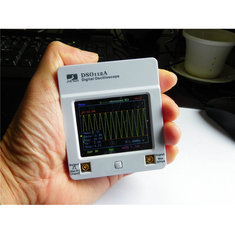
With its dimensions of 79 by 69 by 18 mm, the DSO112A is probably the smallest oscilloscope you can find. It is powered via USB or via a built-in battery, has an analog bandwidth of 2 MHz and a sensitivity of 2 mV/div. You operate this low frequency oscilloscope via the touchscreen. |
Introduction to the DSO112A of JYE Tech
Fits in the palm of your hand
In the figure below we have shown the small dimensions of this oscilloscope. The DSO112A of JYE Tech is a single channel low frequency oscilloscope that is powered from 5 Vdc through the well-known micro USB connector that is standard on portable devices today. The device draws about 300 mA of current from this power supply. However, you can order a 3.6 V Li-ion battery as an extra. The oscilloscope has only one push button as control element. This switches the device on or off and switches from measuring (Run) to signal freezing (Hold) during operation. All other functions can be set by clicking the checkboxes on the screen with a fingernail.
 |
| The dimensions of the DSO112A. (© Banggood.com) |
It will be clear that there is no room for the standard BNC connectors on such a small oscilloscope. The designers have therefore chosen for two miniature connectors of the MCX type. This acronym stands for Micro CoaXial. MCX is an HF connector that was developed in the mid-eighties to connect HF equipment. The two connectors are gold plated and have a diameter of only 3.6 mm. Because you do not have measuring probes with such connectors, an adapter cable from MCX to BNC is included.
 |
| Comparison of the dimensions of an MCX connector with your familiar BNC. (© 2020 Jos Verstraten) |
In the figure below we have uncovered the electronics in the DAO112A. The electronics are built around two Atmel microprocessors, both with RISC architecture. These processors, a Mega64A and a Mega88PA, have a built-in ten bit wide ADC, of which only eight bits are used in this design. The picture also shows the extra battery to be purchased, which has a capacity of 1,200 mAh and must be mounted on top of the main PCB.
 |
| The internal electronics of the DSO112A. (© 2020 Jos Verstraten) |
The DSO112A is, without internal battery, for sale directly from various Chinese mail order companies for a price between € 30.00 and € 80.00, including shipping to the Netherlands. For that money you get:
- The DSO112A oscilloscope.
- A 40 cm long cable with two crocodile clamps and an angled MCX connector.
- A 10 cm long cable with a BNC female and a MCX connector.
- A 120 cm long USB cable with a USB-A and a micro-USB connector.
- A 1/1 or 1/10 probe with BNC connector.
 |
| What's in the box of the DSO112A. (© JYETech) |
Technical specifications of the DSO112A
Vertical channel specifications
- Number of channels: 1
- Analogue bandwidth: 0 Hz ~ 2 MHz
- Sensitivity: 2 mV/div ~ 20 V/div
- Inaccuracy: less than 5 %
- Resolution: 8 bit
- Input impedance: 1 MΩ
- Input voltage: 50 Vpeak-to-peak maximum
- Coupling: DC, AC, GND
- Cursors: two
- Automatic measurements: Vmin, Vmax, Vpp, Vrms, Vavr
Horizontal channel specifications
- Sampling rate: 5 Ms/s maximum
- Time base: 1 µs/div ~ 50 s/div
- Sample memory: 512 or 1,024 samples
- Cursors: two
- Automatic measurement: frequency
Specifications trigger functions
- Trigger modes: auto, normal, single
- Trigger types: rising or falling edge
- Trigger position: 1/8, 1/4, 1/2, 3/4 or 7/8 of sample memory
- Trigger sources: internal, external
- External trigger voltage: 15 Vpeak-to-peak max.
Signal generator specifications
- Frequency: 1 Hz ~ 10 Hz ~ 100 Hz ~ 440 Hz ~ 1 kHz ~ 10 kHz ~ 100 kHz ~ 1 MHz
- Signal shape: square wave
- Amplitude: 3.3 V
Power supply specification
- Voltage: 3.7 V Li-ion battery or 5 Vdc via micro-USB
- Current: 300 mA
Other specifications
- Case dimensions: 79 mm x 69 mm x 18 mm
- Weight: 85 g
- Display: 2.4 inch color TFT/LCD touch screen
- Memory for 24 settings
- Save current screen
- Recall of saved screen
- Measurement samples as CSV file to Windows PC with additional software
- Firmware upgrade via Windows PC with additional software
Working with the DSO112A
Starting up the DSO112A
After connecting a 5 Vdc USB power supply, just press the single push-button on the device. The firmware starts up the system, an activity that takes about twelve seconds and is accompanied by three startup screens. Afterwards, you will see the Select Preset screen (see later) which will remain on screen for eight seconds, allowing you to select one of 24 preset settings. If you do not react, the oscilloscope screen will be displayed afterwards. You can now connect the signal to be observed to the vertical input and set the oscilloscope using the various menus.

The DSO112A screen
You will see all kinds of messages in color, which you need to touch to select a particular function or give you information about the current status of the device.
- Menu:
Clicking this text will put the main menu on the screen, see later. - Trigger position:
Provides information about which sample in memory is used for triggering. - Horizontal position:
By moving this slider back and forth with your finger, you scroll through the stored samples. - Run/Hold indication:
Indicates whether the DSO112A is measuring the actual signal or whether the last measurement is frozen on the screen. - Trigger level:
By moving this purple arrow up and down you can select the signal level to be triggered. - Trigger source:
Indicates which source you have selected, internal or external. - Trigger slope:
Indicates whether you trigger on negative or positive signal slope. - Time base setting:
The chosen time base speed. - Input coupling:
Can be DC, AC or GND. - Sensitivity setting:
The chosen vertical sensitivity. - Vertical position:
By moving this yellow arrow up and down you set the 0 V reference on the screen.
 |
| The meaning of all symbols and texts on the screen. (© 2020 Jos Verstraten) |
The vertical settings
Calling up the vertical menu
By briefly clicking with your fingernail on the yellow text, in the lower left corner of the screen, you call up the menu with which you can change the vertical settings of the scope.
The vertical menu
This is shown in the figure below. On the right, you can set the signal coupling to:
- DC: DC voltage is also passed to the ADC.
- AC: Only alternating current is passed to the ADC.
- GND: Only the 0 V reference line is displayed on the screen.
By clicking on one of the yellow boxes you can set the sensitivity of the vertical amplifier. There are thirteen settings in the known 1/2/5 order from 2 mV/div to 20 V/div. The 2 mV/div option is not shown on this screen, you need to scroll to the previous page with the arrow button. The Done button activates the settings and returns to the oscilloscope screen.
Please note that you are not allowed to apply more than 50 Vpeak-to-peak on the input!
 |
| The menu for the vertical settings. (© 2020 Jos Verstraten) |
The horizontal settings
Calling up the horizontal menu
By briefly clicking with your fingernail on the green text at the bottom center of the screen, you call up the menu that allows you to change the horizontal settings of the scope.
The horizontal menu
The horizontal menu consists of three screens that allow you to set the time base speed in 24 steps in the known 1/2/5 order between 1 µs/div and 50 s/div.
Select Record Lenght
On the rightmost screen you will see the option 512 pts or 1024 pts. This sets the size of the sample memory to 512 or 1,024 samples.
 |
| The time base setting menu. (© 2020 Jos Verstraten) |
The trigger settings
Calling up the trigger menu
You call up this menu by briefly clicking on the purple text at the bottom right of the screen.
The trigger menu
The trigger menu consists of four columns, each of which sets a certain trigger property.
 |
| The menu for setting the trigger functions. (© 2020 Jos Verstraten) |
- AUTO, NORM, SING:
In AUTO mode, the scope will sample the input signal under all conditions and display these samples on the screen. If the device finds a sample in the signal that matches the trigger conditions you set, it will synchronize to it to display a still image. In NORM mode, sampling of the input signal will only start if the signal meets the trigger conditions. If not, the image will freeze on the last recorded series of samples. In SING(le) mode, the scope will only run a sampling cycle once if the trigger conditions are met and then stop. - Pos, Neg:
You can select the rising or falling edge of the signal as trigger condition. - 1/8, 1/4, 1/2, 3/4, 7/8:
This indicates the trigger position in the sample memory. If you select 7/8, you will see the samples in front of this trigger point on the screen. If you select 1/8, you will see the samples after this trigger point. - INT, EXT:
With INT the scope triggers on the signal at the vertical input. With EXT, the device triggers on a signal that you connect to the left connector. Note that you can offer a maximum of 15 Vpeak-to-peak at this connector.
The main menu
Calling up the main menu
This menu is displayed by clicking on the blue text at the top left of the screen.
The main menu
In this menu, you set some basic functions of the oscilloscope.
- VPos Cal:
This option allows you to calibrate the left yellow arrow, which should indicate the zero reference, to 0 V. - Save WF:
The current image is stored in the EEPROM memory of the processor. This storage will survive switching off the device. After switching it on again, you can conjure up this image again with... - Recall WF:
Indeed, with this button. - Send data:
With this option you can send the samples stored in the memory via a USB cable to your Windows PC. You do need extra software for this action. The result is a text file that you can open in Excel, for example. - Default:
Restores all settings to the values as they are when you start up the device. - Preset:
This option allows you to save all your current settings in one of the 24 presets that you can store in memory.
 |
| The main menu of the DSO112A. (© 2020 Jos Verstraten) |
This option allows you to set the test signal to eight different frequencies, see figure below. This signal is a square waveform and has a fixed amplitude of about 3.3 V.
 |
| Setting the test signal frequency. (© 2020 Jos Verstraten) |
This option enables two vertical cursor lines that you can move across the screen. The software calculates the time difference between the two cursors and sets this time difference numerically in the top left corner of the screen.
ΔV
Put two horizontal cursor lines on the screen, the software calculates the voltage difference between these two cursors and puts this numerically in the top left corner of the screen.
V
The software calculates a number of values of the input signal fully automatically:
- The maximum voltage Umax
- The minimum voltage Umin
- The peak-to-peak value Upp
- The average value Vavr
- the root mean square value Vrms
These data appear in the lower left corner of the screen.
Freq
The software calculates the frequency of the input signal and puts it numerically in the lower right corner of the screen.
 |
| The data displayed on the screen after switching on the menu options ΔT, ΔV, V and Freq. (© 2020 Jos Verstraten) |

DSO112A mini 2 MHz scope