|
With its dimensions of 57 mm by 34 mm by 11 mm you can call Daniu's DSO188 a matchbox oscilloscope. If you think this device is nothing more than a funny, but useless toy you are wrong. It allows you to observe signals up to 100 kHz. We tested this miniature wonder of Chinese technology. |
Introduction to the DSO188
The delivery of the scope
The DSO188 is delivered under the brand name Daniu and can be purchased via the well-known Chinese internet channels for prices from € 21.86. The scope is delivered in a sturdy cardboard box containing the device in an ESD-safe bag, a micro USB charging cable, a BNC to MMCX adapter and a BNC measuring cable of 50 cm with two large crocodile clamps at the end. There is also a sturdy A5 sheet in the box with, in microscopic small script, the full manual of the scope in English.
 |
| The contents of the DSO188 package from Daniu. (© 2018 Jos Verstraten) |
Thanks to the simple sandwich construction of front panel, PCB and rear panel, you can quickly open this scope and study the inside electronics. We did that for you, in the picture below you can see the amazingly small amount of electronics present on the PCB.
The heart of the circuit is of course a microcontroller of the type GD32F103RCT6 from GigaDevice. This controller has a maximum clock speed of 108 MHz, has 256 kB flash memory and 48 kB RAM on board and works with 16 bit wide analog to digital converters. Of course, the circuit contains all the ingredients for direct control of the TFT-LCD screen.
You will also see a 74HC40510 analogue multiplexer, two 356T optical couplers and an OptoMOS relay CPC1008N. These chips are undoubtedly used for the automatic electronic switching of the sensitivity of the input attenuator. We could imagine that the CPC1008N is used to switch from the DC to AC coupling of the input signal, where a capacitor has to be included in the signal path.
 |
| The electronics on the PCB of the DSO188. (© 2018 Jos Verstraten) |
- Maximum sampling frequency: 5 Msamples/s
- Sampling: 12 bit
- Memory space: 40,000 samples
- Analog bandwidth: 1 MHz
- Analog sensitivity: 50 mV/div ~ 20 V/div in 9 ranges
- Maximum input voltage: 40 V peak-to-peak
- Input impedance: 1 MΩ
- Input coupling: AC/DC
- Rise time: less than 100 ns
- Time base: 100 ms/div ~ 2 μs/div in 15 ranges
- Triggering: leading edge/trailing edge
- Display: color TFT screen 36 mm x 30 mm
- Power supply: 5.0 V via 1 A USB charger
- Internal battery: 3.6 V lithium, 250 mAh
- Dimensions: 57 mm x 34 mm x 11 mm
- Weight: 40 g
Charging the battery
The first thing to do is to charge the built-in lithium battery from a 5 Vdc power supply. It has a capacity of 230 mAh and a voltage of 3.7 V. The manual warns that you should not charge this battery from a USB port on your laptop because it cannot provide the 1 A charging current. Use a 5 V USB charger that can provide at least 1 A. With a fully charged battery you can, at least according to the manual, use the scope continuously for about two hours.
Working with the DSO188
The basic operation of the DSO188
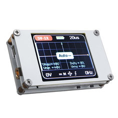
A total of seven push buttons are available for the operation of the scope. For some functions you have to press two buttons at the same time, working with this scope requires some practice. However, it is very easy to put an oscillogram on the screen. Connect the signal to be measured to the MMCX connector on the left side of the scope. Activate the scope with the slide switch on the right side. That's all! The scope enters the automatic mode and determines the necessary settings of the input attenuator and the time base to get a good view of the input signal on the screen. However, what the DSO188 thinks is a good image is not always your idea of a good image. In most cases you will have to adjust both values by hand. You can do this by pressing the four upper buttons. With the two left buttons you set the sensitivity of the scope, with the two buttons next you set the time base. If you want to return to the automatic mode, briefly press the AUTO/MAN button, after which the DSO188 again puts its idea of a good image on the screen.
If you want to freeze the image for a while, press the RUN/HOLD button and the scope will save the image in memory and will not continue sampling.
 |
| The push button operation of the DSO188. (© 2018 Jos Verstraten) |
The first function of the MODE push button is to switch the function of the four buttons next to it. If you press this button briefly, the ⊕ symbol at the bottom of the screen changes to one with four arrows. You can then use the four other top buttons to move the oscillogram up, down, left and right. A second press of the MODE button restores the ⊕ symbol and you can set gain and time base again.
In addition, by pressing the MODE button together with another button you can set the following functions of the scope. In practice, you must first press and hold the MODE button, then press and release the second button and finally release the MODE button.
- MODE + RUN/HOLD
Triggering on the positive or negative slope of the signal. - MODE + LOWER SENSITIVITY
DC or AC coupling of the input signal. - MODE + FASTER TIME BASE
The input sensitivity is reduced by a factor of ten to compensate for the use of a 1/10 measuring probe. - MODE + SLOWER TIME BASE
Enables or disables the display of numerical measurement data Vmax, Vmin, Vrms and Duty on the screen. - MODE + HIGHER SENSITIVITY
The DSO18 enters the self-calibration mode. This means that the yellow arrow, on the right of the screen and showing the zero reference, will be calibrated to 0 V. Before operating these two buttons, it is absolutely necessary to remove both the input signal and the USB charging cable from the device. When you operate these two push buttons, a window appears with the text 'Calibration?'. If you want to recalibrate the zero reference, press the MODE button again. After a few seconds the text 'Calibrating Successful' will appear.
 |
| The DSO188 is ready to calibrate the GND reference. (© 2018 Jos Verstraten) |
The DSO188 displays up to six numerical values of the measured signal:
- Vmax
The maximum value of the measured signal. - Vmin
The minimum value of the measured signal. - Vrms
The calculated root-mean-square value of the signal. - Vptp
The peak-to-peak value of the measured signal. This value appears in a larger font on the lower left of the grid. - Duty
The percentage ratio between 'H' and 'L' in a digital pulse. - Freq
The frequency of the measured signal. This value appears on the right under the grid in a larger font.

Important note
The manufacturer clearly states in the manual that all these measured values are 'for reference only'. And indeed, as the tests will show, the values displayed are quite different from the actual values.
The DSO188 on the test bench
The useful life on one battery charge
We did not reach the two hours promised in the manual. After ninety minutes our scope stopped working. Afterwards, the scope has to load at least two hours again to achieve the same useful life.
A 100 kHz square wave signal
We tested the representation of a square wave signal with a frequency of 100 kHz and a peak to peak value of 8 V. Both quantities are checked on our 100 MHz lab-scope. What the DSO188 makes of it is shown in the picture below. The signal reproduction is excellent for such a cheap device. The oscillogram appears quietly on the screen and the scope triggers stable.
We are much less impressed by the accuracy of the voltage display and the numerical data on the screen. With a sensitivity of 2 V/div an 8 V square wave signal should be really four divisions high. This is not the case, so there is quite a lot wrong with the accuracy of the voltage divider at the analog input of the device. This is also shown by the numerical representation of the amplitude that is represented as 6.80 V instead of the 8.0 V that the signal really is. Also with the reproduction of the frequency we discover a rather big error, which should not happen with a block-shaped signal.
 |
| A square wave with a frequency of 100 kHz and a peak-to-peak value of 8.0 V. (© 2018 Jos Verstraten) |
Here (of course) the same problem reveals itself. The signal display is satisfactory, the voltage calibration of the scope is worthless. Now our DSO188 even claims that the 8.0 V sine is only 6.60 V large.
 |
| A sine wave with a frequency of 100 kHz and a peak-to-peak value of 8.0 V. (© 2018 Jos Verstraten) |
Displaying a narrow pulse is a difficult task for most cheap oscilloscopes. The DSO188 performs relatively well. In the picture below you can see how this scope represents a pulse with a width of 1 μs. Now not only is the amplitude measurement completely confused, but also the frequency measurement is not correct. The frequency of this narrow pulse was 100 kHz and not 160 Hz, as the DSO188 claims.
 |
| A narrow pulse with a width of 1.0 μs. (© 2018 Jos Verstraten) |
The reproduction of small signals on a digital scope is often affected by quantisation noise. Especially with such a small device where there is no proper separation between the analog and digital circuits, a capacitive coupling can easily occur between the analog input and for example the clock signal. The DSO188 performs very well, see picture below. We captured a 1 kHz sine wave with an amplitude of 50 mV on the screen of the DSO188. Moreover, you can see that the algorithms that calculate the amplitude and frequency from the samples are now doing a good job. Also the amplitude on the screen is nicely displayed as exactly two divisions high.
 |
| A 1 kHz sine wave with an amplitude of 50 mV. (© 2018 Jos Verstraten) |
In this last test we set the scope to DC coupling and put a 100 Hz block of exactly 10 V at the input. The result is excellent, both in terms of signal shape and measurement accuracy.
 |
| A 100 Hz square wave of 10 V is perfectly reproduced. (© 2018 Jos Verstraten) |
Our opinion on the DSO188
Of all the cheap oscilloscopes we have tested, we are the most impressed with this DSO188. Despite the small dimensions, the scope is easy to operate and the oscillogram is easy to interpret. It is easy to live in practice with a service life of about ninety minutes with one battery charge.
The only unfortunate thing about this beautiful device is that the DSO188 cannot be used to reliably measure the numerical values of the input signal. The manufacturer should have omitted this option, because a measurement function that is 'for reference only' is not very useful in practice.

DSO188 Pocket Digital Ultra-small Oscilloscope