Introduction to the DSO3D12 from Zeeweii
The appearance of the device
Measuring just 14.5 cm by 8.6 cm by 3.2 cm, the device looks really cute. A gadget of the first order! But, tech geeks like us are obviously not seduced by such looks, but want to put all the specifications to the test.
The DSO3D12 has a multi-colour screen measuring 65 mm by 50 mm and is controlled by 24 push buttons. These are close together but are still easy to operate individually. Most push buttons have a dual function. The black text on the buttons indicates the primary function, the white text on the housing the secondary. That secondary function becomes active after pressing the 'Shift↑' key.
Below the display are the four 4 mm banana plug sockets you need when using the device as a multimeter. These are made to accept fully insulated banana plugs as well.
The back contains a fold-out bracket that allows you to place the device at an angle on your hobby desk so that it is easy to read and operate.
On the top are the two BNC connectors of the two oscilloscope inputs, the output of the function generator (two large solder tabs), the USB-C connector for charging the battery and the ON/OFF button.
 |
| The appearance of the DSO3D12. (© 2024 Jos Verstraten) |
Manufacturer, suppliers, prices
The DSO3D12 is developed by China's Shenzhen Zeeweii Instrument Co., Ltd. from (obviously) Shenzhen. This company exclusively markets non-professional oscilloscopes at very reasonable prices. The DSO3D12 is the latest addition to their product range. It is a very popular device and can be bought through various sellers on AliExpress and Amazon, but also, for example through Banggood. At AliExpress, at the time of writing this article, you will pay € 105.91 for it, at Banggood € 109.78.
What you get for your money
The DSO3D12 comes in a neat little box, together with:
2 x oscilloscope measuring probe with switchable 1/10 attenuator
2 x fully insulated multimeter measuring probe
1 x USB-C to USB-A cable
1 x set of accessories for the oscilloscope measuring probes
1 x a well-written 18-page manual in English
Protected from shipping damage, the meter itself is prepacked in a styrofoam frame.
 |
| The scope of delivery of the DSO3D12. (© AliExpress) |
The manual
We have put it on our account on the 'Internet Archive':
The highlights of the DSO3D12
- At the touch of a button, you can turn the DSO3D12 into a full-screen oscilloscope, multimeter or function generator.
- According to the specifications, the oscilloscope's bandwidth in single-channel mode is no less than 120 MHz! That value drops to 60 MHz if you activate both channels. Of course, we are going to check that.
- Again according to the manual, the oscilloscope has a rise time of less than 3.0 ns, a more than excellent value for such a cheap device (if true).
- Both the oscilloscope and the multimeter work fully automatically, meaning that the software is able to make the right selections to get the best possible image or measurement of the input signal.
- A rather unique feature is that you can control the DSO3D12 with your voice. In the current version of the software, twenty English-language commands are recognised.
- You can save the oscilloscope screens to the internal memory at the touch of a button and take them out to put back on the display.
- The multimeter measures up to 5999 or 9999 counts and has a lowest measurement range of 599.9 mV.
- You can insert the multimeter and the function generator screens in small windows in the oscilloscope's display.
- The four inputs of the multimeter are galvanically isolated from the oscilloscope by means of an isolation transformer and optical couplers. You can measure with the multimeter in a completely different device or circuit without these measurements affecting the measurement of the oscilloscope. Ground-loop problems can therefore not occur.
- You can put fourteen numeric data of the signals on both input channels on the oscilloscope's screen.
- You can put two vertical and two horizontal cursors on the screen and make precision voltage and time measurements.
- You can switch the oscilloscope to X/Y mode and put the famous Lissajous figures on the screen.
- At the touch of a button, you can make the instantaneous oscillogram the reference. It turns red and remains static on the display. Afterwards, you can easily compare newly measured signals with this reference oscillogram.
- The DSO3D12 oscilloscope has a zoom mode that allows you to display a part of the oscillogram enlarged.
- With a few simple actions with the push buttons, you can calibrate the DSO3D12 multimeter by comparing the readout with that of a more accurate multimeter.
What we like less about the DSO3D12
- The multimeter's '10A' input is not protected by a fuse! That means you can damage the internal of the device quite a bit if, when measuring between this input and the 'COM', you do something wrong such as measure a high-energy voltage.
- You cannot manually set the multimeter's measuring range.
- You can put the images stored in memory back on the screen, but not manipulate them further, for instance by setting the time base differently. They are and remain static pictures.
- You cannot access the screenshots stored in memory via the USB cable to export them to a PC for illustrating purposes.
- The output voltage of the function generator is not adjustable, which rather limits the practical usefulness of this measuring device.
- The output signal of the function generator is available only on two solder tabs and not on a third BNC connector.
- The trigger functions of the oscilloscope are rather limited, so a fully stable image does not always appear on the screen. Especially at higher frequencies, the oscillogram jitters a bit on the screen.
- The FFT option in this oscilloscope is nice to have a look at, but has no useful application.
The front panel with the control buttons
The picture below shows the front panel of the DSO3D12 with all the control buttons.
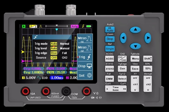 |
| The front panel with the control buttons. (© Banggood) |
General specifications
- Housing material: ABS
- Display: 3.2 inches IPS colour
- Battery: 2,500 mAh lithium
- Charging: USB-C 5.0 V
- Charging current: 700 mA
- Operating language: Chinese or English
- Voice interface: 20 English commands
- Dimensions: 14.5 cm x 8.6 cm x 3.2 cm
- Weight: 252 g
Oscilloscope specifications
- Number of channels: CH1 and CH2
- Bandwidth: 120 MHz for CH1 only, 60 MHz for CH1 and CH2
- Rise time: less than 3 ns
- Real-time sampling rate: 250 MSa/s
- Equivalent sampling rate: 500 MSa/s via software algorithm
- Sample memory: 128 kB
- Sensitivity: 10 mV/div to 10 V/div in 10 steps 1-2-5
- Input resistance: 1 MΩ
- Coupling: AC/DC
- Maximum input voltage: 40 V
- Probe attenuation compensation: 1/10/100
- Time base: 5 ns/div to 10 s/div in 28 steps 1-2-5
- Trigger mode: auto/normal/single
- Trigger signal: CH1 or CH2
- Trigger start: rising or falling edge
- Trigger level: auto or manual
- On-screen numeric data: 14 per channel
- Persistence: none ~ 1 s ~ ∞
- XY mode: yes
- Screenshot: yes
- FFT: yes
- Auto set: yes
- Zoom mode: yes
Function generator specifications
- Frequency range sine wave: 10 Hz ~ 5 MHz
- Frequency range other signals: 10 Hz ~ 2 MHz
- Duty cycle square wave: 1 % ~ 99 %
- Number of signal shapes: 8
- Output voltage: 2.5 Vpeak-to-peak, not adjustable
Multimeter specifications
- Number of counts: 5999/9999
- Measuring ranges DC voltage: 599.9 mV ~ 5.999 V ~ 59.99 V ~ 599.9 V
- Accuracy DC voltage: ±[0.5 % + 3]
- Measuring ranges AC voltage: 599.9 mV ~ 5.999 V ~ 59.99 V ~ 599.9 V
- Accuracy AC voltage: ±[1.0 % + 3]
- Measuring ranges DC current: 59.99 mA ~ 599.9 mA ~ 9.999 A
- Accuracy DC current: ±[2.0 % + 3]
- Measuring ranges AC current: 59.99 mA ~ 599.9 mA ~ 9.999 A
- Accuracy AC current: ±[3.0 % + 3]
- Measuring ranges resistance: 599.9 Ω ~ 5.999 kΩ ~ 59.99 kΩ
- Measuring ranges resistance: 599.9 kΩ ~ 5.999 MΩ ~ 59.99 MΩ
- Accuracy of resistors: ±[1.0 % + 3] to ±[3.0 % + 3]
- Measurement ranges capacitors: 59.99 nF ~ 599.9 nF ~ 5.999 µF
- Measurement ranges capacitors: 59.99 µF ~ 599.9 µF
- Measurement ranges capacitors: 59.99 µF ~ 599.9 µF
- Accuracy capacitors: ±[10 % + 5] to ±[15 % + 5]
- Measuring range diodes: 0.0 V ~ 3.3 V
- Measuring range continuity: 50 Ω max.
The electronics in the DSO3D12
You can open the unit by unscrewing four bolts on the back of the housing. The battery is attached in the back half of the housing, the electronics in the front half. The battery is connected to the PCB with a small cable. The picture below shows what is involved in creating a device with as many features as the DSO3D12.
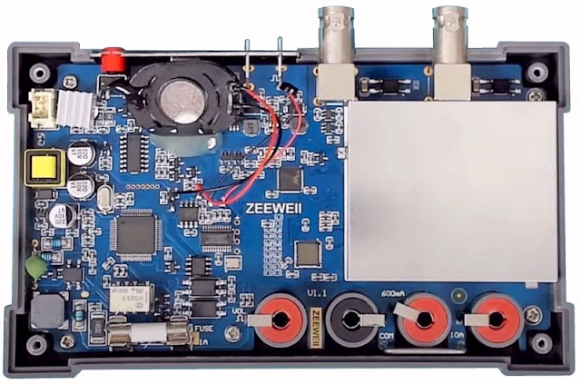 |
| The internal of the DSO3D12. (© 2024 Jos Verstraten) |
The unprotected 10 A shunt sits, all the way on the edge of the PCB and against the housing, under the '600mA' 4 mm banana plug socket. So if you accidentally connect the mains voltage between the 'COM' and the '10A' you can expect, with bad luck, some nice fireworks on this part of the PCB! In the bottom left corner, you can see the isolation transformer and the two optical couplers that galvanically isolate the multimeter part of the circuit from the rest of the electronics. The coding of many of the applied chips has been made unreadable. What is recognisable is a W806-C200 microcontroller from Xiamen WINWIN Electronic. The voice recognition is built around a US665P31 Voice Recognition Chip from UniSound. Interestingly, the microphone capsule dangles loosely inside the device on two wires. Beneath the metal shield are the two linear preamplifiers of the oscilloscope's two channels.
Selecting the functions of the DSO3D12
Switching on the device
Press the red button on the top of the device until you hear a beep. The DSO3D12 immediately starts up in the 'single-channel oscilloscope' function with only 'CH1' active.
Selecting one of the four remaining functions
Now press the red button again, the screen below appears. Use the cursor keys to select one of the five icons. Press the blue 'OK/Auto' button to activate the relevant function.
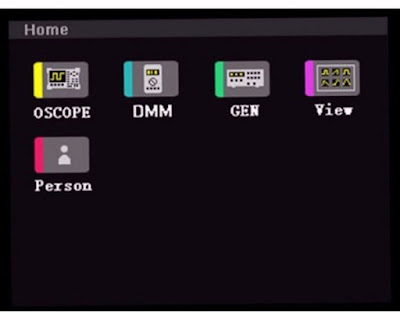 |
| Selecting the main functions of the DSO3D12. (© 2023 Zeeweii) |
The 'Personalisation' function
In the screen below, you can customise a few visual properties of the display to suit your own taste. You can display the grid as a full or dotted line, set the colour of the grid and of the second channel, define the size of the multimeter's screen, and invert the display's colours if you wish.
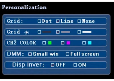 |
The screen of the 'Person' function. (© 2023 Zeeweii) |
The 'Image View' function
In this function, you can see all the screenshots you have stored in memory via the 'Save' key. Using the cursor keys, you can navigate in this screen, delete screenshots or put them on the screen using the 'OK/Auto' key.
 |
| The 'View' function screen. (© 2023 Zeeweii) |
The 'Signal generator' function
In the screen below, you can use the cursor keys and the 'OK/Auto' key to set all the specifications of the function generator. The '50.0%' option allows you to control the duty-cycle of the output pulse. Unfortunately, as already written, it is not possible to set the size of the output signal, which is and remains 2.5 Vpeak-to-peak.
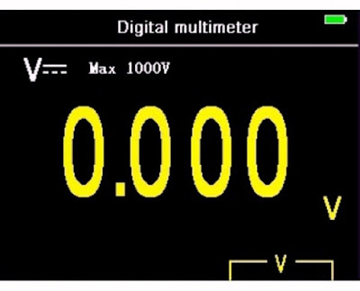
The multimeter starts up in the DC voltage measurement function, see the picture below. You immediately see between which banana plug sockets you should connect the signal to be measured, a handy extra. The multimeter only works with automatic range selection, manual setting of a measuring range is not possible.
 |
| The screen of the 'Digital multimeter' function. (© 2023 Zeeweii) |
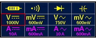
Of course, you must manually select the quantity to be measured. This is done by briefly pressing the 'Select' key. Using the cursor keys and the 'OK/Auto' key, you can then select the quantity to be measured in the window below. For voltages, you can select an extra sensitive measuring range of 599.9 mV. For currents, you can select a range of 10.00 A. Again, remember that this input is not internally protected!
 |
| Selecting the quantity to be measured. (© 2023 Zeeweii) |
Working with the oscilloscope function
Activating 'CH2'
As already written, the oscilloscope always starts up in the mode where only 'CH1' is active. The advantage is that you then have the maximum bandwidth of 120 MHz at your disposal. If you also want to use 'CH2', press 'Shift↑' and then 'CH1/CH2'. You will then see the purple baseline of the second channel also appear on the screen.
Setting numeric measurement data
For both channels, you can set fourteen numeric measurement data on the screen. Press the 'Menu' button and the window below will appear on the display. You can now select the parameters of 'CH1' to be displayed. You do this, as always with this little device, by selecting with the cursor keys and confirming with the 'OK/Auto' button. Ready? Then press the 'Single' key and you can select the numeric data for 'CH2'. Forgot something from 'CH1'? Then press the 'Stop' key to return to the setting of 'CH1'. You leave this window by pressing the 'Menu' key again.
 |
| Selecting the numeric measurement data. (© 2024 Jos Verstraten) |
And now... just measure!
Connect the two signals to be measured to the two BNC connectors and press the 'OK/Auto' button. You will hear some relay clicking and after a few seconds the signals will be on the screen as good as possible. Sensitivity and time base are automatically set to what the software thinks is the best value. Of course, that doesn't necessarily mean you agree with that choice!
All data on the display
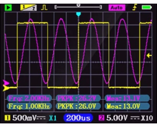
In the picture below, you can see what kind of data the software puts on the display. The green square in the top left corner indicates that the oscilloscope is active. After pressing the 'Stop' button, this obviously turns red. The box '1/2' informs you of which of the two channels you can vary the position on the screen with the cursors '▼' and '▲'. In this example, that is 'CH1'. If you want to change the position of 'CH2', just press the 'CH1/CH2' button. The white scale with the blue arrow at the top of the screen indicates which part of the samples stored in memory you see on the screen. You can change that with the '◄' and '►' cursors.
The yellow and purple arrows on the left of the screen indicate the zero position of both channels. The yellow arrow on the right indicates the trigger level.
The bottom line shows the data of both channels and the time base setting. The 'x1' and 'x10' indicate the attenuation of the measurement probes. That data is automatically incorporated into the sensitivity settings and numerical data. You set that attenuation factor for 'CH1' by pressing the 'x1x10' button. For 'CH2', you must first press the 'Shift↑' button. You can compensate probe attenuations of 1/1, 1/10 and 1/100 in this way.
 |
| The standard display when measuring with the oscilloscope. (© 2023 Zeeweii) |
Setting time base and attenuation
This is easy with the push buttons 'Time base', 'ch1' and 'ch2'.
Setting the triggering
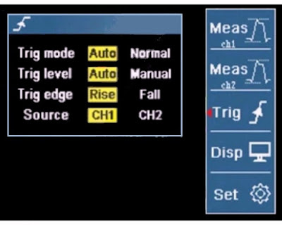
The DSO3D12 has fairly limited trigger capabilities. However, for most signals that you want to see stably on the screen, these settings are completely sufficient. Press the 'Menu' key and then the 'AC/DC' key. The options of the trigger menu are shown in the image below. The available options are clear! If you choose 'CH2' as the 'Source', the arrow on the right will obviously turn purple.
What is not yet obvious is how to manually set the trigger level. Press the 'Shift↑' key and then the '▼' and '▲' cursors. You will now see the right-hand yellow or purple arrow move up and down.
 |
| Selecting the trigger functions. (© 2024 Jos Verstraten) |
Saving a screen dump
Press the 'Save' button and the current screen is saved to memory. The screen briefly displays the message 'SAVE DONE'. All screen dumps are recalled by first pressing the 'Shift↑' key and then the 'Save' key.
Inserting the 'Gen' and 'DMM' windows
While using the DSO3D12 as an oscilloscope, you can put the measurement result of the multimeter and the setting of the function generator as small windows over the oscillogram. Use the 'Gen' and 'DMM' keys to do this.
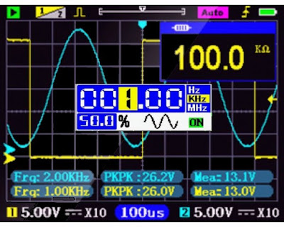 |
Inserting the mini windows of 'Gen' and 'DMM'. (© 2024 Jos Verstraten) |
Special functions of the oscilloscope
Introduction
You can now get started with the DSO3D12 oscilloscope. In most cases you will also not need more than what we have discussed so far. However, the oscilloscope has some interesting additional features. We would do the little device a great injustice if we left these unmentioned.
Voice control with twenty voice commands
Not discussed in the manual, but present in the device is the ability to control the device with your voice. You can speak twenty English-language commands that the software recognises. You access this capability by first pressing the 'Shift↑' key and then the bottom of the 'Ch1' key. You must precede each command with the words 'hello Zeeweii'.
The commands to which the device responds are:
- auto setting
- single
- run
- stop
- AC/DC coupling
- mV 1
- V 1
- TB second
- nano second
- XY mode
- back to scope
- channel two on
- channel two off
- save picture
- enter view page
- test resistance
- test DC voltage
- multimeter diode
- test continuity
- turn off power
The X/Y mode
In this mode, the time base is switched off, the signal on 'CH2' controls a light spot on the screen back and forth and the signal on 'CH1' controls the spot up and down. You enter this mode by first pressing the 'Shift↑' key and then the top of the 'ch1' key.
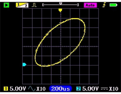 |
| The screen in X/Y mode. (© 2023 Zeeweii) |
The Zoom mode
If you want to view a signal curve both globally over a long time and specifically over a short time interval, you can use the 'Zoom' function. You switch it on by first pressing the 'Shift↑' button and then the 'Stop' button. You can use the 'Time base' buttons to set the zoom factor. The zoomed-in part of the signal appears on the lower part of the screen. Using the '◄' and '►' cursors, you can move the part being zoomed in to the left or right.
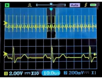 |
The screen in zoom mode. (© 2023 Zeeweii) |
The cursor measurements
You can set two horizontal and two vertical green cursor lines. This way, you can measure time and voltage differences. You enter this function by first pressing the 'Shift↑' and then the left or right side of the 'Timebase' key. Using the '◄', '►', '▼' and '▲' keys, you can move the four lines around the screen. A window in the top left of the screen displays the time and voltage difference ∆Y between the cursor lines. This allows you to measure, for example, the magnitude of a voltage spike or the rise time of a signal.
 |
| The screen during cursor measurements. (© 2024 Jos Verstraten) |
The FTT mode
This mode allows you to visualise the frequency composition of a signal below the time oscillogram. Note that even the manufacturer admits that this FTT analysis of the signal with the DSO3D12 works extremely primitive and you can make absolutely no measurements with it. You won't get more than an overall impression of the frequency composition of a signal.
You enter FTT mode via the buttons 'Menu','DMM' and then with the cursors to the option 'FFT'. Then select, again with the cursors, the options 'Log', 'Lin' or 'Music'. Confirm with 'OK/Auto' and press 'Menu' again. The result is shown in the figure below. Analysed is a square wave with a frequency of 1 kHz. In red, you can see the FFT analysis with a linear horizontal frequency scale. You can see how the amplitude of the harmonics decreases. It's fun to look at for a while, but its practical use is zero.
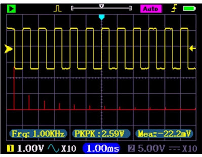 |
The screen in FFT mode. (© 2023 Zeeweii) |
Reference-waveforms
This option allows you to 'freeze' the two current oscillograms on the screen. These images are then displayed in red and blue and remain on the screen as a reference. This way, you can compare the oscillogram of a new signal with this reference. You activate this option by first pressing the 'Shift↑' and then the 'Single' key. In the same way, you exit this option.
 |
| The screen showing the two 'Reference waveforms'. (© 2023 Zeeweii) |
Testing the function generator
The sine wave output at 5 MHz
In the oscillogram below, you can see the sinusoidal output voltage of the function generator at the maximum frequency of 5 MHz on the screen of our XDS2102A oscilloscope from Owon. You can clearly see signal distortions, but we have seen much uglier 5 MHz sine waves coming out of cheap Chinese function generators.
 |
| The 5 MHz sine wave from the function generator. (© 2024 Jos Verstraten) |
Sine wave distortion analysis at 1 kHz
This is a bit disappointing! At 1 kHz, the DSO3D12 delivers a sine wave with a total harmonic distortion of 2.35 %. The oscillogram below shows the output signal on the left (top) and the harmonic distortion filtered out of it (bottom). So the distortion is mainly second harmonic. On the right, you can see a magnification of the sine wave and how the analogue sine wave voltage consists of a stepped approximation of the ideal sine wave form. This is obviously a property of any digital sine generator, but it is very nicely demonstrated here.
 |
Distortion analysis on the 1 kHz sine wave. (© 2024 Jos Verstraten) |
The rectangular output at 2 MHz
The square wave voltage at the maximum frequency of 2 MHz looks much better than we are used to in our tests of similar low-cost equipment.
 |
The rectangular output voltage at 2 MHz. (© 2024 Jos Verstraten) |
Testing the oscilloscope
Measuring the rise time
The rise time is specified as smaller than 3 ns. We are used to that Chinese manufacturers always specify this characteristic much better than the actual value. This can be done with relative impunity, as most users of their equipment are unable to measure this rise time. We can, so we are curious.
We use a PCB called 'Fast Edge Pulse Generator' for this purpose, which provides a rectangular signal of 1,000 MHz with rise and fall times guaranteed to be less than 180 ps. That value is negligible compared to the rise times of the DSO3D12. So you can conclude that the rise time you see on the screen is caused by the electronics in the device. This PCB plugs directly into the BNC input of the oscilloscope. So cable parameters cannot affect the display of the signal. The results of this test are shown in the figure below. The specified rise time of less than 3 ns is nonsense, we measured 6.0 ns.
 |
| Measurement of the rise time of the DSO3D12. (© 2024 Jos Verstraten) |
Measuring the bandwidth
Bandwidth is another specification that is grossly exaggerated by most Chinese manufacturers. We once tested a cheap Chinese oscilloscope that was specified with a bandwidth of 100 MHz. When measured, it turned out to be about 32 MHz! So again, we are very curious to see what the DSO3D12, with its specified bandwidth of 120 MHz in single-channel mode, gets out of it.
The best method to check the bandwidth of an oscilloscope is to use a very wide-bandwidth sine generator. Of course, the prerequisite is that this device is guaranteed to have an absolutely straight amplitude/frequency characteristic. This means that if you set an output voltage of 1.0 V, the device delivers an output voltage of 1.0 V at all frequencies. Our sine wave generator TF2015 from Marconi meets this requirement.
Such a measurement goes as follows. You first apply a signal at a frequency of 10 MHz and place the horizontal cursor lines at the peaks of the sine wave. You slowly increase the frequency, obviously leaving the sensitivity of the oscilloscope in the same position. You see the signal on the screen getting smaller and smaller. Somewhere there is a frequency at which the peak-to-peak value of the sine wave becomes equal to 70% of the distance between the two cursor lines. That is the bandwidth of the oscilloscope.

We performed this measurement on the DSO3D12 and use frequencies of 10 MHz, 50 MHz and 100 MHz. To eliminate the heavy capacitive load of the input of the oscilloscope, we work with a well-tuned 1/10 probe with a bandwidth of 100 MHz.
The results are summarised in the figure below. It clearly shows that the frequency response of the DSO3D12 is absolutely straight up to 50 MHz. At 100 MHz, the height of the oscillogram dropped to 60.6 % of the value at 10 MHz. So the bandwidth is not 120 MHz, but we estimate it to be somewhere around 80 MHz based on the images. Not an unsympathetic value for such a cheap little device!
 |
| Measurement of the bandwidth of the DSO3D12. (© 2024 Jos Verstraten) |
Display a perfect 50 MHz sine wave
In the picture below of the DSO3D12's screen, you can see how this device displays a perfect 50 MHz sine wave from our TF2015 generator from Marconi. You will notice that the display at the bottom of the sine is somewhat distorted and that one peak is lower than the other. Apparently, the sin(x)/x interpolation that is responsible for the screen display is already having some difficulty at 50 MHz in constructing an accurate image from the 250 MSa/s sampling rate.
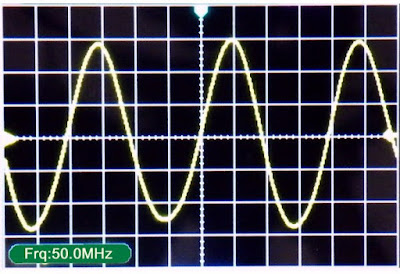 |
The display of a perfect 50 MHz sine wave. (© 2024 Jos Verstraten) |
Display of a perfect 1 MHz square wave
Our PCB 'Fast Edge Pulse Generator' produces a perfect square wave with a frequency of exactly 1 MHz. The screen shot below shows how the DSO3D12 reproduces this signal.
 |
The display of a perfect 1 MHz square wave. (© 2024 Jos Verstraten) |
Testing the multimeter
Accuracy at DC voltage
We use various DC voltage sources and resistance dividers to cover a range from approximately 1 mVdc to approximately 1,000 Vdc. We consider the measurements of our Fluke 8842A as 100 % reference and calculate the percent deviation of the DSO3D12's measurements from this reference. Neatly, the tested specimen remains well below the specified deviation of ±0.5 % for all measurements over 100 mV. The automatic measuring range selection works quickly and accurately.
 |
| Accuracy in measuring DC voltages. (© 2024 Jos Verstraten) |
Measuring DC currents
We put the DSO3D12 in series with our ET3255 multimeter from East Tester on a power supply switched as a current source. The table below compares the measurement results.
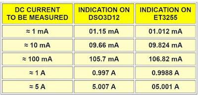 |
| Measuring DC currents. (© 2024 Jos Verstraten) |
Measuring resistors
Measuring capacitors
Measuring 50 Hz AC voltages
The frequency range in AC voltage measurements
We have tested a number of such cheap Chinese 3-in-1 meters over the past year and we could never get very excited about them. The actual performance was a lot below what the specifications promised. However, with the DSO3D12 Zeeweii has in our opinion set a new standard in the market for such multifunctional devices, which the competition can take an example from. Indeed, we are quite pleased with this small, cute and inexpensive device, We can recommend it almost without any reservations to every hobbyist, who wants to buy some beginner measuring equipment and does not yet want to spend a lot of money on it.
That 'almost without any reservation' in the previous sentence refers to the fact that the ten-amp current input is not internally fused. That is a not excusable cutback, especially for a device that will mainly end up with hobbyists.
What we particularly like is the quick way you switch the DSO3D12 from full-screen oscilloscope to full-screen multimeter with a nice and clear layout on the screen in both cases. Because in daily practice it rarely happens that you measure with both a multimeter and an oscilloscope at the same time, this is a very useful and convenient option.
The only thing we really miss in this DSO3D12 is the possibility to set the output voltage of the function generator to a desired value. We understand that for such a price, it is not possible to build a very wideband software-controlled voltage attenuator into the electronics. But, why not opt for a frequency range up to only 500 kHz sine wave with the possibility of adjusting the output voltage via the software with the push buttons? That would be more useful than a non-adjustable 5 MHz sine wave, a frequency that does not have very many practical applications.
Finally, we would have liked the generator's output to be available on a BNC connector. We find those two bulky solder tabs a bit amateurish.
For this test, we have at our disposal a set of reference resistors with a tolerance of ±0.01 % plus some less accurate ones. As a reference meter, we obviously use our 8842A from Fluke. The 8842A uses a four-wire kelvin probe, which is not possible with the DSO3D12. The results are again summarised in a table.
 |
| Measuring resistors. (© 2024 Jos Verstraten) |
Measuring capacitors
Thanks to a set of five accurate capacitors with a tolerance of ±1 % and three reference capacitors with a tolerance of only ±0.05 %, we can test the performance of the DSO3D12. Above 1 µF, we measure ordinary electrolytics from our stock. As a reference meter, we use East Tester's ET4401 with an accuracy of ±0.2 % for non-electrolytic capacitors.
As might be expected, the DSO3D12 measures small capacitors with a fairly large error. A capacitor of 100 pF is not even recognised. This is a characteristic of almost all instruments that measure capacitors with only two wires instead of a four-wire probe, as real RLC meters do.
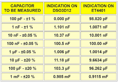 |
| Measuring capacitors. (© 2024 Jos Verstraten) |
Measuring 50 Hz AC voltages
In most cases, you use the AC voltage function of a multimeter to measure 50 Hz voltages. Hence, we tested this with a function generator for small voltages and with a variac for the larger ones. Our ET3255 from EastTester is used as a reference meter. Once again, the measurements with the DSO3D12 prove that you can rely on them.
 |
| Measuring 50 Hz AC voltages. (© 2024 Jos Verstraten) |
The frequency range in AC voltage measurements
This is not specified. In most cheap digital multimeters, it does not go beyond a few kHz. We check this by measuring a voltage of 1 Vrms and varying frequency with the DSO3D12. The ET3255 is again used as a reference meter. The result is summarised in the table below. So also with this device you will not get beyond a few kHz, at 3 kHz you are already at a deviation of about 10 %.
 |
| The frequency range in AC voltage measurements. (© 2024 Jos Verstraten) |
Our opinion on Zeeweii's DSO3D12
We have tested a number of such cheap Chinese 3-in-1 meters over the past year and we could never get very excited about them. The actual performance was a lot below what the specifications promised. However, with the DSO3D12 Zeeweii has in our opinion set a new standard in the market for such multifunctional devices, which the competition can take an example from. Indeed, we are quite pleased with this small, cute and inexpensive device, We can recommend it almost without any reservations to every hobbyist, who wants to buy some beginner measuring equipment and does not yet want to spend a lot of money on it.
That 'almost without any reservation' in the previous sentence refers to the fact that the ten-amp current input is not internally fused. That is a not excusable cutback, especially for a device that will mainly end up with hobbyists.
What we particularly like is the quick way you switch the DSO3D12 from full-screen oscilloscope to full-screen multimeter with a nice and clear layout on the screen in both cases. Because in daily practice it rarely happens that you measure with both a multimeter and an oscilloscope at the same time, this is a very useful and convenient option.
The only thing we really miss in this DSO3D12 is the possibility to set the output voltage of the function generator to a desired value. We understand that for such a price, it is not possible to build a very wideband software-controlled voltage attenuator into the electronics. But, why not opt for a frequency range up to only 500 kHz sine wave with the possibility of adjusting the output voltage via the software with the push buttons? That would be more useful than a non-adjustable 5 MHz sine wave, a frequency that does not have very many practical applications.
Finally, we would have liked the generator's output to be available on a BNC connector. We find those two bulky solder tabs a bit amateurish.


