|
For half a euro you can buy this module that allows you to switch on and off low-power light bulbs with a capacitive touch contact. We investigated how this module works and whether it is reliable. |
Getting to know the DY-11 touch sensor switch
The appearance
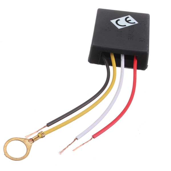
This plastic module, which is offered under different type numbers, measures 45 mm x 35 mm x 14 mm. One side contains a large slot from which four wires of 9 cm come out. These wires do not have the same colours in all models, but the order is always the same. If you hold the module with the wires facing left, the correct order is from top to bottom:
- Life wire of the 230 V mains.
- Switching wire to a lamp.
- Sensor wire.
- Neutral wire of the 230 V mains.
The sensor wire ends in a 15 mm diameter open brass ring that is capacitively connected to the electronics in the module. The second connection of the lamp goes to the neutral of the mains, of course.
 |
| The appearance of the DY-11 module. (© Tech Club Store) |
What the module does
The DY-11 module is a touch switch. A bit of electronics that switches 'something' on or off when you touch a metal contact. In this case, that 'something' is a low-power 230 V lamp, which can be either filament or LED. The module switches lamps up to 40 W on and off. Please note that this module does not dim or operate three ways, like some of its kind. Between the modes 'ON' or 'OFF', these modules have a third mode 'DIM', in which the lamp is dimmed to a fixed set value.
The electronics in the DY-11 module
The printed circuit board
In the plastic housing is the PCB shown below, measuring 40 mm by 30 mm. What immediately attracts attention is that a very low power triac in TO-92 has been selected: a MAC97A6. This type has a maximum current of 0.6 A and a maximum on-state voltage of 1.9 V. The total thermal resistance is 150 °K/W. So, if we assume a maximum heating up to +75 °C, this triac can dissipate about 0.5 W of power. That corresponds to a maximum current of about 250 mA.
This current provides, at the mains voltage of 230 V, a maximum power of about 55 W. The manufacturer's specified power of 40 W therefore seems to be a safe value.
It should be noted that the PCB offers the possibility to replace the MAC97A6 with a type in TO-220 housing. The BT136 is specified on the silkscreen. This type can switch 4 A. By soldering this semiconductor into the PCB and removing the MAC97A6 from the PCB, you can considerably increase the maximum switching power.
The IC is marked K101 which is, according to internet sources, a clone of the well-known chip TT6061A.
 |
| The small PCB inside the module. (© 2021 Jos Verstraten) |
The circuit diagram of the DY-11 module
In the figure below, we have reconstructed the schematic from the PCB layout. The first thing that strikes you is that the touch contact is only connected to the rest of the circuit via one capacitor C5. That is a potentially life-threatening decision by the designer(s). It is true that this very small capacitor is marked '1kV', but these are only numbers and letters! If this capacitor becomes defective and shorts internally, there is only a 150 kΩ resistance between the contact and the circuit directly connected to the mains voltage. For comparison: in the schematic advised by the manufacturer of the TT6061A there are three capacitors in series.
 |
The schematic of the DY-11 module. (© 2021 Jos Verstraten) |
VERY IMPORTANT ADVICE
If you are going to use this module, we strongly advise you to install a second capacitor between the touch electrode and the PCB. This can be a capacitor of 100 nF and 400 V. We have tested this in practice.
The DY-11 module in practice
Connecting the module
The following illustration shows the connection diagram of this module once more. The extra capacitor we recommend is included.
 |
| The wiring diagram of the DY-11 module. (© 2021 Jos Verstraten) |
The quiescent current of the module
In the OFF state, the module draws a current of 6.9 mA from the mains voltage. This corresponds to an idle power of 1.59 W.

Testing the module with a 40 W incandescent lamp
Naturally, we tested the module with the maximum load specified by the manufacturer, a 40 W light bulb. For safety reasons, the test was performed via an isolation transformer. The picture below shows the voltage across the lamp. This clearly shows that the lamp is not being supplied with the full half-periods, but that there is a small phase angle after the zero crossing in which the lamp is not powered. However, this phase angle is so small that this phenomenon has no noticeable effect on the intensity of the light. The flattening of the tops of the sine wave has nothing to do with the operation of the module, but with the fact that the circuit is powered by an isolation transformer.
 |
The voltage across the 40 W bulb. (© 2021 Jos Verstraten) |
The thermal behaviour of the module
We have drilled a 1.5 mm hole in the middle of the housing and clamped a thermocouple in it. We measure the rise of the internal temperature in the module under continuous load with the 40 W bulb. The results are summarised in the graph below. After half an hour, the internal temperature in the module has risen to 65.0 °C. After one hour the temperature stabilises at 66.8 °C.
By the way, the material of the housing insulates very well. On the outside, the module does not heat up to more than thirty degrees.
Naturally, we are curious as to who is responsible for this thermal energy. That is mainly the 2 W resistor R1, which heats up to 169.2 °C. This resistor seems to be a metal oxide film resistor (MOF). According to the specifications, such resistors are allowed to heat up to 155 °C. This resistor gets a little too hot and is also located on the PCB. It would be better to mount such a component a few millimeters above the surface of the PCB so that there is better air circulation and the PCB does not heat up so much.
The triac keeps to a comfortable 31.9 °C. This last measurement will not be entirely exact because the housing of a TO-92 is so small that even bringing it into contact with a small thermocouple will cause a noticeable drop in temperature.
 |
| The temperature rise in the module. (© 2021 Jos Verstraten) |
Testing the module with a 10 W LED lamp
We have repeated the test with a 10 W LED lamp. It switches on and off without any problems. However, the voltage across the lamp looks rather strange, see the oscillogram below. These oscillations have nothing to do with the type of lamp. Other LED lamps also show the same picture. This phenomenon is also not a consequence of the power supply via the isolating transformer. The secondary transformer voltage offered to the module looks good. Somehow the interaction between the electronics of the module and the electronics in a LED lamp causes these oscillations on the lamp voltage.
 |
| The voltage across the 10 W LED lamp. (© 2021 Jos Verstraten) |
Our conclusion about the DY-11 module
It will be clear that we cannot recommend this module, despite its extremely low price. It is a shame that the designers only included one capacitor between the touch electrode and the module's internal electronics. The thermal power dissipated in the 2 W resistor is too high. A component that gets +170 °C on a small PCB cannot improve the long-term reliability of this module.
What would it cost extra if the designers had opted for a slightly larger casing, creating room for a second 2 W resistor and a second 1 kV capacitor, and better cooling in the module? Even if this would push up the selling price of this module to € 2.00, we would still consider it a bargain. The result would be a safer and more reliable product!
But of course you can use this module as a cheap start for a self-designed touch switch with better safety specifications. And thus this unworthy product still gets a good destination!

Three-Way touch controlled switch