|
With this device from ZKE Tech, you can not only test all kinds of batteries, but also test DC power supplies up to 30 V. You can test the device up to 20 A or up to 200 W, whichever comes first. |
Getting to know the EBD-A20H from ZKE Tech
What can you do with the EBD-A20H?
This device allows you to test a power supply or a battery with a constant current between 100 mA and 20 A for a time to 999 minutes. The device measures time, voltage and current and calculates the power in watts, the energy in watt-hours and the capacity in amp-hours. This data is shown on the display.
In addition, you can also test the connected device with a constant power up to 200 W. The device then calculates the current from the measured terminal voltage.
For both measurements, you can set a so-called 'cut-off' voltage, at which the measuring cycle is automatically terminated. This way, you can experimentally answer questions such as 'if I unload my 12 V battery with 1.5 A, how long does it take until the voltage drops to 10.8 V'?
Even more interesting, you can connect the EBD-A20H to your PC and use the downloadable software 'EB Tester' to turn it into a real logger. This way, you can document both described measurement cycles by displaying the measurement data of voltage and current in a graph as a function of time or by exporting the measurement data as a TXT file.
With the 'Auto Test' function of the software, you can program a fully automatic measuring cycle where, for example, the current increases by 100 mA every other minute until the cut-off voltage is reached.
Price and delivery
This electronic load is offered for a price starting from € 54.60 at AliExpress. However, shipping is € 21.88. We ordered our test specimen from Banggood for € 87.50. The device is delivered in a cardboard box and in this box, it is packed in a very sturdy air cushion packaging. Despite the weight of the device, the chance of damage during transport from China seems minimal.
 |
| The packaging of the EBD-A20H. (© 2021 Jos Verstraten) |
Scope of delivery
The EBD-A20H is supplied including:
- Two 50 cm long thick flexible leads for the current.
- Two 50 cm long thin flexible leads for the voltage.
- One 90 cm long TTL to USB cable.
- One 12 V @ 1 A mains power supply with 90 cm long cord and American plug.
- An American to European plug adapter.
- A 16 pages manual, in Chinese only.
The four test leads have solid crocodile clips on one side. The thick current leads end at the other side in large copper ring cable lugs with a current capacity of 30 A. These have to be screwed under the 4 mm big banana sockets on the EBD-A20H. The two thin voltage leads end in rather unprofessional 4 mm banana plugs. The screws, for example, are touchable. Although the device is obviously only intended for working with voltages of up to 30 V, we still do not like plugs with touchable live parts. Who knows what else the user will use these cables for!
The TTL to USB cable has a large USB-A connector at one end, which contains a piece of electronics, read more. At the other side this cable ends in a very sturdy four-pole screw connector. However, the rather thin cable is placed in this connector without any strain relief, which seems rather unreliable in the long run.
The supplied power supply has American flat pins, but an adapter to European round pins is included. The power lead terminates in a standard 5.5 mm x 2.1 mm connector.
 |
| The scope of delivery of the EBD-A20H. (© 2021 Jos Verstraten) |
The EBD-A20H electronic load
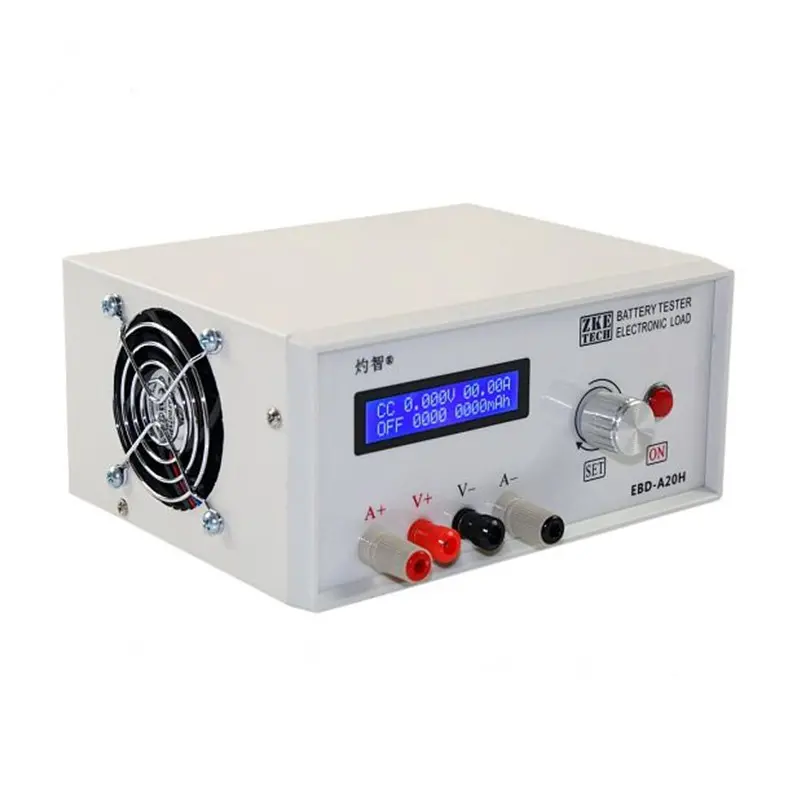
The unit itself is housed in a sturdy metal case 190 mm wide, 100 mm high and 150 mm deep and weighs 1.8 kg. On the front there is the well-known standard LCD display HD44780 with 2 x 16 characters, a rotating encoder 'SET' which you can also press and a push button 'ON' with which you start or stop a measuring cycle. You can connect the four supplied leads to four 4 mm banana sockets. This four-wire technique minimises measurement errors when measuring the voltage of the battery or power supply. If you would work with only two leads, the voltmeter in the EBD-A20H would not measure the correct voltage, but the terminal voltage minus the voltage drop over the connecting leads. With a maximum current of 20 A, this voltage drop is not negligible. The four-wire technology allows the voltmeter to be connected directly to the terminals of the device under test, measuring the real voltage independent of the current drawn.
The two 4 mm sockets for the current are quite large, as they must be able to handle a current of 20 A without heating up too much.
On the back you see the ON/OFF push button switch, the connector for the 12 V power supply and the four-pole screw connector for the TTL-USB interface cable. What gave the designers the idea of putting the ON/OFF switch in such an awkward place is a mystery to us. This switch only turns on the 12 Vdc of the mains power supply and there is enough space on the front panel to incorporate this switch. If, like us, you have collected a 'wall' of instruments and want to place this EBD-A20H in a suitable spot among them, then a switch on the back of a device is a real disaster.
The right side of the housing is almost completely taken up by a ventilation grid with slots of 3 mm width. The left side contains a large fan, protected by a grid with very large openings.
The four rubber feet ensure a stable and slide-proof positioning on your work table.
The specifications of the EBD-A20H
According to the manufacturer ZKE Tech, this electronic load meets the following specifications:
- Supply voltage: 12 Vdc / 1 A
- Cut-off voltage setting range: 0 V ~ 30 V
- Voltage setting resolution: 10 mV
- Current setting range: 0.10 A ~ 20 A
- Resolution current setting: 10 mA
- Resolution measurement voltage: 1 mV
- Accuracy of voltage measurement (0,0 V ~ 4,5 V): 0,003 V ±0,5 %
- Accuracy of voltage measurement (4.5 V ~ 30 V): 0.001 V ±0.5 %
- Resolution measurement current: 10 mA
- Accuracy of current measurement: 0,01 A ±0,5 %
- Power continuous: 180 W
- Power peak: 200 W
- Indications: voltage ~ current ~ power ~ capacity ~ time
- Function DSC-CC: load with constant current
- Function DSC-CP: load with constant power
- Dimensions: 190 mm width x 100 mm height x 150 mm depth
- Weight: 1.8 kg
The unit itself is housed in a sturdy metal case 190 mm wide, 100 mm high and 150 mm deep and weighs 1.8 kg. On the front there is the well-known standard LCD display HD44780 with 2 x 16 characters, a rotating encoder 'SET' which you can also press and a push button 'ON' with which you start or stop a measuring cycle. You can connect the four supplied leads to four 4 mm banana sockets. This four-wire technique minimises measurement errors when measuring the voltage of the battery or power supply. If you would work with only two leads, the voltmeter in the EBD-A20H would not measure the correct voltage, but the terminal voltage minus the voltage drop over the connecting leads. With a maximum current of 20 A, this voltage drop is not negligible. The four-wire technology allows the voltmeter to be connected directly to the terminals of the device under test, measuring the real voltage independent of the current drawn.
The two 4 mm sockets for the current are quite large, as they must be able to handle a current of 20 A without heating up too much.
 |
| The front and rear of the EBD-A20H. (© 2021 Jos Verstraten) |
On the back you see the ON/OFF push button switch, the connector for the 12 V power supply and the four-pole screw connector for the TTL-USB interface cable. What gave the designers the idea of putting the ON/OFF switch in such an awkward place is a mystery to us. This switch only turns on the 12 Vdc of the mains power supply and there is enough space on the front panel to incorporate this switch. If, like us, you have collected a 'wall' of instruments and want to place this EBD-A20H in a suitable spot among them, then a switch on the back of a device is a real disaster.
The right side of the housing is almost completely taken up by a ventilation grid with slots of 3 mm width. The left side contains a large fan, protected by a grid with very large openings.
The four rubber feet ensure a stable and slide-proof positioning on your work table.
The specifications of the EBD-A20H
According to the manufacturer ZKE Tech, this electronic load meets the following specifications:
- Supply voltage: 12 Vdc / 1 A
- Cut-off voltage setting range: 0 V ~ 30 V
- Voltage setting resolution: 10 mV
- Current setting range: 0.10 A ~ 20 A
- Resolution current setting: 10 mA
- Resolution measurement voltage: 1 mV
- Accuracy of voltage measurement (0,0 V ~ 4,5 V): 0,003 V ±0,5 %
- Accuracy of voltage measurement (4.5 V ~ 30 V): 0.001 V ±0.5 %
- Resolution measurement current: 10 mA
- Accuracy of current measurement: 0,01 A ±0,5 %
- Power continuous: 180 W
- Power peak: 200 W
- Indications: voltage ~ current ~ power ~ capacity ~ time
- Function DSC-CC: load with constant current
- Function DSC-CP: load with constant power
- Dimensions: 190 mm width x 100 mm height x 150 mm depth
- Weight: 1.8 kg
The electronics in the EBD-A20H
Unscrewing the housing
After removing nine screws, you can remove the U-shaped top of the housing from the U-shaped bottom. Both parts are still connected to each other via the cable that supplies power to the fan. This cable is attached to the PCB with an easily removable connector.
As you can see in the picture below, the interior of the device mainly consists of a large heatsink, a PCB on this heatsink for controlling the MOSFETs and a small PCB that is screwed onto the front panel.
The interior of the device looks neat. All soldered wires are finished with heatshrink and the wires are neatly bundled along the edges of the case.
What is immediately noticeable is that the four MOSFETs are screwed to the heatsink without insulation. Closer examination reveals that the heatsink is mounted on the bottom of the case in an insulated manner. However, the distance between the bottom of the heatsink and the bottom of the case is very small. In our opinion, it should have been a few millimetres more! Especially as this heatsink is only screwed to the bottom with two screws and can therefore move back and forth.
 |
| The interior of the EBD-A20H. (© 2021 Jos Verstraten) |
The driving of the MOSFETs
The four MOSFETs on the heatsink are of type URFP250M. These semiconductors have an RDS(on) of 0.075 Ω and an ID of up to 30 A. The maximum power dissipation is 214 W. So this part of the circuit seems to be heavily over-dimensioned. Of course, that can never do any harm! In the picture below, you can see that next to the four MOSFETs there is a KSD-01F H090. This is a temperature switch that closes at a temperature of 90 °C. It is used to control the fan. It works at two speeds. When the device is switched on, it works at a low speed. If the heatsink gets warmer than 90 °C, the fan switches to a higher, rather noisy speed.
On this PCB there are four RX21 resistors of 0.1 Ω and 6 W. They divide the current between the four MOSFETs. The thick red and black wires go to the 4 mm sockets on the front panel. You can easily follow the circuit: from the black wire via a wide PCB track to the two current sensor resistors RC11 and RC12, via a wide PCB track to the four 6 W resistors, to the MOSFETs and from the MOSFETs via a wide PCB track back to the red wire. It is strange that only the top one of the three wide PCB tracks has been provided with a sloppy amount of solder. The purpose of this is completely unclear to us!
In the top left corner is the PCB connector for connecting the fan.
 |
| The PCB on the heatsink for driving the MOSFETs. (© 2021 Jos Verstraten) |
The electronics behind the front panel
On this PCB we discover quite a lot of electronics. An OP213F from Analog Devices, an op-amp with a very low offset of only 100 μV. Two LM358A's, a double op-amp. One CD4053, a triple analogue switch. One STM8S105K4, an 8 bit wide microcontroller that contains the intelligence of the device and with its 10 bit wide ADC converts the analogue values to be measured into digitally processable data. The rotary encoder is on a small additional PCB connected to the main PCB via a PCB header.
 |
| The PCBs behind the front panel of the EBD-A20H. (© 2021 Jos Verstraten) |
The TTL to USB cable
This four-wire cable, a standard Prolific PL2303, is connected to +5 Vdc, ground, RXD and TXD. This way the device can communicate in two directions with the downloadable software. The large USB-A connector is glued and not accessible, but there are enough pictures on the internet to show you what is inside, see picture below.
 |
| The internal of the PL2303 TTL to USB-A connector. (© AliExpress) |
Working with the EBD-A20H
Starting up
When the unit is switched on, the following information is shown on the top line of the display:
- CC: the mode is set to 'constant current'.
- 0.000V: the output voltage of the connected device.
- 00.00A: the current supplied by the connected device.
And on the bottom line:
- OFF: the mode of the device, now obviously 'OFF'.
- 0000: the measurement cycle time, not yet set.
- 0000mAh: the capacity supplied.
 |
| The data on the display after switching on. (© 2021 Jos Verstraten) |
Connecting the battery or power supply
Next, connect the device or component to be tested to the EBD-A20H using the four cables supplied. The voltage display now shows the voltage of the connected device.
Setting mode to DSC-CC or DSC-CP
Press the 'SET' button for at least two seconds. By turning this button, you can select the two modes:
- DSC-CP: Load with constant power.
- DSC-CC: Load with constant current.
Setting the parameters in DSC-CC
In this mode, the display changes to something that looks like the figure below. By pressing the 'ON' button you can quickly set one of the following three parameters. By pressing and turning the 'SET' button, you can scroll through the figures and set them one by one to the desired value:
- The load current (A): adjustable between 100 mA and 20.00 A.
- The cut-off voltage (V): adjustable between 10 mV and 30.00 V.
- The time (Min): adjustable between 1 minute and 999 minutes.
If you set the time to 000Min, a measurement cycle will last until you stop it.
Then press the 'SET' button for more than two seconds. The settings are saved.
 |
| The data on the display when DSC-CC is selected. (© 2021 Jos Verstraten) |
Setting the parameters in DSC-CP
The display shows the data represented in the figure below. The indication of the current now changes to the indication of the power delivered. You can set this parameter with a resolution of 1 W. Again, press 'SET' for more than two seconds to save the settings.
 |
| The data on the display when DSC-CP is selected. (© 2021 Jos Verstraten) |
Starting a measurement cycle
Briefly press the 'ON' button to start the measurement cycle. The indication 'OFF' in the display changes to 'DSC'. The connected device is now loaded or discharged with the current or power set by you. By briefly pressing the 'SET' button, you can switch between displaying the total delivered power in mWh or the total delivered capacity in mAh. Similarly, you can switch between the display of the elapsed time of the measurement cycle or the instantaneous delivered power in W.
 |
| The data on the display during measurement. (© 2021 Jos Verstraten) |
Ending a measurement cycle
Press 'ON' to end the measurement cycle. By pressing the 'SET' button, you will see the delivered power (which is now zero, of course), the total duration of the cycle, the total delivered capacity (mAh) or the total delivered energy (mWh).
The cooling and the internal temperature
We have a 12 V power supply that can deliver a maximum current of 30 A. An ideal device to judge the performance of the EBD-A20H. However, 12 V times 30 A gives a power output of 360 W and the EBD-A20H cannot handle that. At the moment the test starts, the processor ensures that the current consumption drops to 17.12 A. With the terminal voltage of the power supply dropped to 11.68 V, this corresponds neatly to a power consumption of 200 W.
In another test, we read that the two current leads are far too thin and become blisteringly hot at maximum load. We didn't notice any of this during our test with 17 A. Even after half an hour, these leads were no more than comfortably warm. After about ten minutes, the fan switched to full speed. After half an hour, the temperature of the air in the outlet of the fan was measured as 35.3 °C. A thermocouple was used to measure the temperature of the heatsink: 92.5 °C.
The accuracy of the voltage measurement
We connected the EBD-A20H to a digitally adjustable power supply and compared its voltage indication with that of our Fluke 8842A reference meter. The results are shown in the table below and we think they are excellent.
The accuracy of the current measurement
We created a series circuit of the power supply, the EBD-A20H and our Voltcraft VC650BT meter and set the current on the EBD-A20H. The results of these measurements are summarised in the table below. We cannot measure higher than 10 A, we had already accidentally blown the fuse in our Fluke by a too high current! These results are also excellent.
Installing the software
You can download the software from www.zketech.com. The RAR file contains:
- An English manual.
- The installation file for the software.
- The installation file for the USB driver.
First install the software and then the USB driver. On our old-fashioned Windows 7 system, this was no problem.
Open the software and only then connect the EBD-A20H to your PC with the supplied cable. In the 'Com Setting' window (bottom right) select the COM-port to which the device is connected. In our case, it was COM7, but this can differ from PC to PC, depending on what USB drivers are already installed on your PC.
Then click on the 'Connect' button in the same window and communication between your PC and the device should start. The EBD-A20H will display '-PC-' and you should now operate the unit from the PC.

Version 1.8.5
Here we briefly discuss the options of version V.1.8.5 of the software. At the time of reading this article, a newer version of the software may of course be available.
The 'Single Test' option
In this mode you operate the device through the software in the same way as you do through the buttons on the front panel. The figure below shows the results of a test of three LGDAHB31865 Li-ion 3.7 V batteries with a capacity of 1,500 mAh discharged in parallel at a current of 10 A. The blue line shows the evolution of the slowly decreasing voltage, the red line shows the constant current of 10 A. Of course you can export the data in various ways. The 16-page manual is comprehensive and written in understandable English ( a compliment for a Chinese product!), so we will not go into that further.
The 'Auto Test' option
This option allows you to test the connected battery with a current that is stepwise increased. You can set the following parameters:
- The start current (Start Curr).
- The end current (Stop Curr).
- The step current (Step).
- The cut-off voltage (Volt).
- The step time (Change).
After clicking the 'Start'-button the EBD-A20H, fully controlled by the software, tests the connected power supply or battery with a stepwise increasing current and you can see in the graph what the consequences are on the voltage. In the 'Run Data' window, the voltage, current and power output are recorded per step.

(Banggood sponsor ad)
EBD-A20H Electronic Load
Press 'ON' to end the measurement cycle. By pressing the 'SET' button, you will see the delivered power (which is now zero, of course), the total duration of the cycle, the total delivered capacity (mAh) or the total delivered energy (mWh).
A few simple tests with the EBD-A20H
The cooling and the internal temperature
We have a 12 V power supply that can deliver a maximum current of 30 A. An ideal device to judge the performance of the EBD-A20H. However, 12 V times 30 A gives a power output of 360 W and the EBD-A20H cannot handle that. At the moment the test starts, the processor ensures that the current consumption drops to 17.12 A. With the terminal voltage of the power supply dropped to 11.68 V, this corresponds neatly to a power consumption of 200 W.
In another test, we read that the two current leads are far too thin and become blisteringly hot at maximum load. We didn't notice any of this during our test with 17 A. Even after half an hour, these leads were no more than comfortably warm. After about ten minutes, the fan switched to full speed. After half an hour, the temperature of the air in the outlet of the fan was measured as 35.3 °C. A thermocouple was used to measure the temperature of the heatsink: 92.5 °C.
The accuracy of the voltage measurement
We connected the EBD-A20H to a digitally adjustable power supply and compared its voltage indication with that of our Fluke 8842A reference meter. The results are shown in the table below and we think they are excellent.
 |
| Test of the accuracy of the voltmeter. (© 2021 Jos Verstraten) |
The accuracy of the current measurement
We created a series circuit of the power supply, the EBD-A20H and our Voltcraft VC650BT meter and set the current on the EBD-A20H. The results of these measurements are summarised in the table below. We cannot measure higher than 10 A, we had already accidentally blown the fuse in our Fluke by a too high current! These results are also excellent.
 |
| Test of the accuracy of the ammeter. (© 2021 Jos Verstraten) |
The 'EB Tester' software
Installing the software
You can download the software from www.zketech.com. The RAR file contains:
- An English manual.
- The installation file for the software.
- The installation file for the USB driver.
First install the software and then the USB driver. On our old-fashioned Windows 7 system, this was no problem.
Open the software and only then connect the EBD-A20H to your PC with the supplied cable. In the 'Com Setting' window (bottom right) select the COM-port to which the device is connected. In our case, it was COM7, but this can differ from PC to PC, depending on what USB drivers are already installed on your PC.
Then click on the 'Connect' button in the same window and communication between your PC and the device should start. The EBD-A20H will display '-PC-' and you should now operate the unit from the PC.
Version 1.8.5
Here we briefly discuss the options of version V.1.8.5 of the software. At the time of reading this article, a newer version of the software may of course be available.
The 'Single Test' option
In this mode you operate the device through the software in the same way as you do through the buttons on the front panel. The figure below shows the results of a test of three LGDAHB31865 Li-ion 3.7 V batteries with a capacity of 1,500 mAh discharged in parallel at a current of 10 A. The blue line shows the evolution of the slowly decreasing voltage, the red line shows the constant current of 10 A. Of course you can export the data in various ways. The 16-page manual is comprehensive and written in understandable English ( a compliment for a Chinese product!), so we will not go into that further.
 |
The window of the 'Single Test' option of the EB Tester software. (© 2021 Jos Verstraten) |
The 'Auto Test' option
This option allows you to test the connected battery with a current that is stepwise increased. You can set the following parameters:
- The start current (Start Curr).
- The end current (Stop Curr).
- The step current (Step).
- The cut-off voltage (Volt).
- The step time (Change).
After clicking the 'Start'-button the EBD-A20H, fully controlled by the software, tests the connected power supply or battery with a stepwise increasing current and you can see in the graph what the consequences are on the voltage. In the 'Run Data' window, the voltage, current and power output are recorded per step.
 |
| The window of the 'Auto Test' option of the EB Tester software. (© 2021 Jos Verstraten) |
EBD-A20H Electronic Load