|
For about fifteen euros, this kit allows you to build a scale with ranges of 99.99 grams and 0.999 kg. Some of the components are supplied as SMD, so some experience with soldering such parts is necessary. |
Introduction to this kit
Manufacturer, suppliers and prices
The manufacturer of this kit cannot be identified, neither on the PCB nor in the building description there is any reference to it. On the PCB it is printed in Chinese 'SSY Rising Electronic Technology'. You can order the kit from the well-known Chinese suppliers. At Banggood you pay € 13.96 for it, at the cheapest supplier we could track down on AliExpress the kit costs € 12.84. We ordered our copy from Banggood.
Delivery of the kit
As unfortunately happens all too often with Chinese kits, too little care is taken with the packaging and shipping. All parts are crammed loosely in a bag that is too small, with the result that in our sample the pins of the microcontroller were bent and it took the necessary attention to get all pins more or less in line again.
 |
The delivery of the parts. (© 2023 Jos Verstraten) |
The delivered parts
In the picture below, we have neatly arranged all the supplied parts. The round disk on the right is the platform on which you place the object to be weighed. This is a solid 5 mm thick disc of plexiglass with a diameter of 85 mm. Below the disk and the PCB you can see a strange aluminum object. This is the sensor called 'load cell', we will come back to this later in this article. More copies of the SMD capacitors and resistors are supplied than you need. That's handy, because if one of those parts jumps out of your tweezers (and it happens easily) you'll never find it again!
 |
| The components of this kit. (© 2023 Jos Verstraten) |
The PCB
The two sides of the PCB are shown in the picture below. In total, you need to solder twelve SMD components on the PCB: one IC, one transistor, five resistors and five capacitors. You can see those on the top right of the PCB. On the bottom left are four transistors. Those are undoubtedly the drivers for the four seven-segment displays. The three pads for the connecting wires of those transistors are so close together that it is almost impossible to solder them without causing a solder bridge. And this while that position is not at all necessary. The three pads could just as well have been in a slightly wider triangle! At the top right is the header H2. The four wires of the sensor come into these four pads.
 |
| The two sides of the PCB. (© 2023 Jos Verstraten) |
The building description
There is a good ten-page English-language construction description on the Internet. We have copied those to our account on Archive.org for you to download:
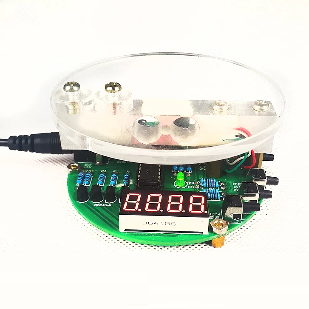
The fully built electronic scale
To give you an idea of what to expect for those fifteen euros, we have photographed our fully built specimen. The device is powered from a 5 Vdc voltage that you can connect to the PCB via a standard 5.5 mm x 2.1 mm power connector.
 |
| The fully built electronic scale. (© 2023 Jos Verstraten) |
The electronics in this digital scale
The load cell sensor YZC-131
The load cell sensor, represented in the picture below, has the type number YZC-131. This part has a weighing range of 0 to 1 kg and is said to have a linearity of ±0.03% over the full scale. Weight is measured using four strain gauges attached to the top and bottom of the bar under a blob of silicone paste and incorporated into a resistance bridge. The resistance of both branches of the bridge is 1 kΩ ±50 Ω. From the bridge come four wires. The bridge is fed between red and black with 5 Vdc and provides an output voltage between green and white. That output voltage is very small and is directly proportional to the distortion applied to the aluminum rod.
 |
| The characteristics of the load cell sensor YZC-131. (© 2023 Jos Verstraten) |
The principle of measurement
In the figure below, we have drawn a very schematic cross-section of the device. The PCB rests stably on three legs. On its right side, the load cell sensor is firmly connected to the PCB by two long bolts. On its left side, the sensor is similarly firmly connected to the platform. If you put something on the platform, the force of gravity exerted on this object will be transferred to the load cell sensor through the left bolts.
The result is that the aluminum rod will deform slightly. This is represented, very exaggeratedly of course, by the dotted line. This deformation causes the resistance bridge in the sensor to become unbalanced and the sensor to deliver a very small DC voltage between its green and white wires. It is inconceivable that such a system is sensitive enough to register objects weighing only a few grams, but it really works!
 |
| The principle operation of the scale. (© 2023 Jos Verstraten) |
Detailed operation of the sensor
It is indeed inconceivable that an aluminum rod would distort under the force exerted by a weight of a few grams. Based on the figure below, the operation of the sensor is discussed in a little more detail.
Very important for its operation is that two holes A and B are drilled in the center of the aluminum rod. These holes are so large that hardly any material remains at the bottom and top. So this creates four very weak points in the construction of the rod. At the top and bottom of the rod, four strain gauges, sensor 1 through sensor 4, are mounted at those points.
If the rod on the left side is loaded with a force F it will result in deformation of the rod between the weak points. This is obviously exaggerated in the figure below. But it can be seen very clearly, thanks to this exaggeration, that sensors 1 and 4 are compressed and sensors 2 and 3 are stretched. The four strain gauges are included in a bridge with the result that the minimum resistance variations of the strain gauges result in maximum output voltage variations.
Processing the sensor voltage
 |
| A slightly more detailed explanation of operation. (© 2023 Jos Verstraten) |
Processing the sensor voltage
The voltage generated by the sensor is so low that a special chip has been developed for amplifying and digitizing such signals. That is the HX711 from AVIA Semiconductor, a 24 bit ADC with two differential input amplifiers. When set to maximum gain, this chip has a measurement range of ±20 mV full scale.
The figure below shows the internal block diagram and the standard circuit around the HX711. The chip also provides the supply voltage for the resistor bridge from a very stable internal bandgap reference. The sigma-delta ADC does not even need an external crystal, but works with an on-chip clock generator.
 |
| The dedicated amplifier and ADC HX711. (© AVIA Semiconductor) |
The full schematic diagram of this electronic scale
In the figure below we have copied the full schematic of this balance from the manual. By clicking on the schematic, it appears larger on your screen.
The switch KEY6 (top left) is the ON/OFF switch of the device. It is located directly behind the 5 Vdc connector DC1. You can power the board from a USB power supply, the circuit consumes about 20 mA of current.
The four switches KEY1 through KEY4 (bottom left) allow you to operate the scale:
- KEY1:
The offset switch, this sets the reading to zero. Is useful if you want to weigh, for example, 50 grams of a powder. You put a dish on the scale, wait until the circuit indicates a stable weight and then press this switch. The readout goes to zero and you can now sprinkle powder into the dish until the display shows 50 grams. - KEY2:
The range switch. Each press of this button switches the range from 99.99 grams to 0.999 kg and then back to 99.99 grams. In the 0.999 kg range, the green LED lights up. - KEY3, KEY4:
You can use these buttons to calibrate the scale. Pressing KEY3 repeatedly raises the reading, pressing KEY4 lowers the reading.
An STC15W408S is used as the microcontroller. This chip manufactured by STC MCU Limited is based on the architecture of the 8051. However, the chip operates faster (about 8 to 12 times the speed of a traditional 8051) and has very low power consumption. No external crystal is required, an RC generator adjustable between 5 MHz and 35 MHz is integrated into the chip.
 |
| The full schematic of this kit. (© 2020 Dayup) |
Construction of the kit
Assembly of the SMD components
If you have little experience soldering SMD components, start by soldering the HX711. First apply a thin layer of tin to all pads, position the chip on the pads with tweezers, and with the tip of the soldering iron, solder one of the corner pins to the pad with very little tin. Do the same with the diagonal corner pin. You can now release the chip and one by one solder all the remaining pins, with very careful addition of some tin, onto the pads. If you manage to assemble this IC without solder bridges and without questionable contacts you can handle the remaining SMD components as well! The code on the parts is:
- Resistors 1 kΩ (R8, R9): 102
- Resistor 20 kΩ (R6): 203
- Resistor 8.2 kΩ (R7): 822]
- Resistor 0 Ω (R16): 0
- Capacitor 100 nF (C2, C3, C4, C5): 104
- Capacitor 10 μF (C6): uncoded

Mounting the axial components
Here the five transistors require extremely careful soldering. The three pads are very close together and a solder bridge between two pads is quickly made!
Note the plus and minus of the two electrolytic capacitors and the flattened side of the LED.
The photo below shows the completely assembled PCB, on which you can mount the load cell sensor and the platform. Don't forget to mount the microcontroller in its socket first!
 |
| The completely soldered PCB. (© 2023 Jos Verstraten) |
Assembling the load cell sensor and platform
This is well explained in the manual with five clear pictures. Once both parts are screwed together on the PCB with the spacers, nuts and bolts, you need to solder the four wires from the sensor to the PCB in H2. The correct order, from top to bottom:
- white
- green
- black
- red
Finally, mount the three 5 mm spacers under the PCB. The picture below shows our final result.
 |
| The end result of our tinkering. (© 2023 Jos Verstraten) |
The electronic scale tested
Want to buy calibration weights?
To calibrate and test a scale, calibration weights of 5 g, 10 g, 20 g, 50 g, 100 g, 200 g, 500 g and 1,000 g are sold. Through AliExpress, you can buy these for € 1.58 each. Performing a Google search for 'Calibration Weight AliExpress' yields a lot of hits. The picture below shows one such set.
 |
A set of calibration weights. (© Roads 4 Store) |
Comparing with a Soehnle
However, we have a rather expensive 1,000 g digital Soehnle scale in our home, left over from our business activities when we had to count all stocked components annually for the tax authorities. We weighed several objects on this scale and compared it to the measurement results of the kit (without further adjustment). You can see the results in the table below. Impressive, aren't they?
 |
Measurement results compared with a SOEHNLE scale. (© 2023 Jos Verstraten) |

Electronic Scale DIY Kit