
|
This small measuring instrument from ToolTop is not only a simple multimeter for voltage, resistance and capacitance, but also a logger for the measurement data and an infrared camera for locating 'hot spots' in electronics. |
Introduction to the ET12S from ToolTop
Manufacturer, suppliers and prices
The manufacturer is probably Feeltech, as the device announces itself on a PC with 'Feeltech' (read on) and the PCB also carries that name. The device is sold under the brand name ToolTop with the type number ET12S. However, we also found the brand name FeelElec with type number FR01C. You can order this multimeter from well-known Chinese suppliers, such as Banggood and perhaps a dozen suppliers working through AliExpress.
At Banggood, you will pay €127.23 for the ToolTop model right now (early September 2023 as a special action). At AliExpress you should expect to pay around €160.00. We found the FeelElec branded model at AliExpress for € 161.39.
So Banggood is clearly the cheapest supplier!
The multimeter, data logger and IR camera ET12S
For what it has to offer, this device is extremely small. Measuring 134 mm by 69 mm by 25 mm and weighing only 125 g, the ET12S fits comfortably in your hand, see photo below.
You operate the meter with four 'real' push buttons below the screen. However, the screen is touch-sensitive, so for other actions you have to click on icons on the display.
The ET12S has only two measurement inputs located at the bottom of the device. In the right side is a USB-3 slot for charging the battery and for data communication with your PC. The meter is powered from an internal 3.7 V battery with a capacity of 850 mAh.
 |
| The ET12S fits comfortably in the hand. (© Banggood) |
The scope of delivery of the ET12S
This one is very limited. The cardboard box contains only the meter plus the two standard test leads that come with every cheap Chinese multimeter. A brief eight-page 'Instruction Manual' describes in good English the capabilities of the multimeter without, however, going into the details of the various options in the multimeter's setup-menu.
 |
| The scope of delivery of the ET12S. (© 2023 Jos Verstraten) |
The external appearance of the meter
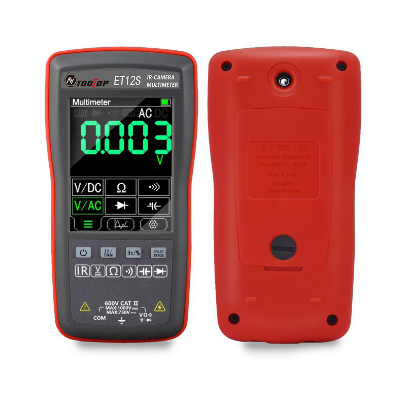
The figure below shows the front and back of the ET12S. At the top of the back is the 'eye' of the thermal camera. This infrared sensitive image sensor has a hardware resolution of 90 by 120 pixels and an aperture angle of 55° horizontally and 35° vertically. This hardware resolution is blown up by the software to a screen resolution of 216 by 288 pixels. The gray screw allows you to open the compartment that holds the battery.
Unfortunately, the ET12S does not have a fold-out bracket on the back that allows you to position the device at a favorable reading angle. This is obviously not possible because of the location of the two measurement sockets on the bottom of the housing.
The front is characterized by a very large color display measuring 58 mm by 44 mm with a resolution of 320 by 480 pixels. The digits are 15 mm high, making them extremely readable. The counting goes up to 4000 for voltage and resistance (and thus not 6000 as claimed by several suppliers). When measuring frequencies, the display counts up to 9999 and for capacitors up to 5120.
In the picture below, the multimeter function is enabled. Selecting the measurement unit is done via the six touch boxes on the display.
 |
| The front and back of the ET12S. (© Banggood) |
Thermal camera specifications
According to the manufacturer, the IR camera has the following specifications.
- IR sensor: UFPA (Uncooled Focal Plane Array)
- Capture frequency: 20 Hz
- Hardware imaging pixels: 90 x 120
- Software imaging pixels: 216 x 288
- Beam angle: 55° (H) and 35° (V)
- Temperature measuring range: -20 °C ~ +400 °C
- Resolution: 0.1 °C
- Temperature measurement accuracy below 0 °C: ±5 °C
- Temperature measurement accuracy above 0 °C: ±2 °C
The specifications of the multimeter
- Number of counts voltage and resistance measurements: 4000
- Number of counts frequency measurements: 9999
- Number of count capacitance measurements: 5120
- Sampling frequency: 6 samples/s
- Measuring ranges DC voltage: 400.0 mV ~ 4.000 V ~ 40.00 V ~ 400.0 V
- Accuracy DC voltage: ±[1.0 % + 3] ~ ±[2.0 % + 3]
- Measuring ranges AC voltage: 400.0 mV ~ 4.000 V ~ 40.00 V ~ 400.0 V
- Accuracy AC voltage: ±[1.0 % + 3] ~ ±[2.0 % + 3]
- Measuring ranges resistance: 400.0 Ω ~ 4.000 kΩ ~ 40.00 kΩ ~ 400.0 kΩ
- Measuring ranges resistance: 4.000 MΩ ~ 40.00 MΩ
- Resistance accuracy: ±[0.5% + 3] ~ ±[1.5% + 3]
- Measuring ranges capacitance: 51.20 nF ~ 512.0 nF ~ 5.120 μF
- Measuring ranges capacitance: 51.20 μF ~ 100.0 μF
- Measuring ranges capacitance: 51.20 μF ~ 100.0 μF
- Accuracy capacitance: ±[2.0 % + 5] ~ ±[5.0 % + 5]
- Measuring range frequency: 9.999 mHz ~ 9.999 Hz ~ 99.99 Hz ~ 999.9 Hz
- Measuring range frequency: 9.999 kHz ~ 99.99 kHz ~ 999.9 kHz
- Frequency accuracy: unspecified
- Measuring range duty-cycle: 0.1% ~ 99.9%
- Duty-cycle accuracy: unspecified
- Diode test: up to 1.5 V
- Continuity test: up to 30 Ω
The electronics in the ET12S
Of course, once again we could not restrain ourselves and stripped down the ET12S. This is done very easily by removing four screws on the back. What is revealed is one PCB that takes up the entire space inside the meter. In the photo below, you can see both sides of this PCB. The manufacturer is apparently very fearful of counterfeiting, because the type numbers of all chips have been made unrecognizable.
The two rectangular cutouts at the bottom of the PCB fit the two 4 mm input sockets, which are soldered directly to the PCB with two metal tabs.
 |
| The two sides of the PCB. (© 2023 Jos Verstraten) |
600 V CAT II?
What we do need to get off our chest is that we find the circuitry around the two input sockets rather fragile. We do not see many large components on the PCB that could serve as protection against overvoltage. There is apparently a small VDR present and a few diodes. Granted, you cannot measure currents with this meter, so there is no chance of measuring mains voltage while the meter is set to current. There are no small impedances between the two input sockets that could generate enormous power in the meter.
But the manufacturer does print '600 V CAT II' and 'Max. 1000 Vdc' on the front panel. We strongly recommend that you keep such voltages far away from the input sockets of this ET12S. Use this meter for low voltage measurements in circuits!
As a test of accuracy, we did briefly connect 1,000 Vdc to the meter, but from a voltage source that can deliver only a few mA. If anything then goes wrong in the meter, that voltage immediately collapses.
Working with the ET12S from ToolTop
Selecting the basic functions
You must select the basic functions using both the four hardware push buttons and the eight software push buttons on the display. These are explained using the figure below.
- A: Power switch of the device.
- B: Switching between multimeter and thermal camera.
- C: Enable Hold function or manual range switch.
- D: Switching to frequency or duty-cycle measurement.
- E: Select measurement functions.
- F: Switching to logger function.
- G: Calling up the Setup menu.
 |
| Selecting the basic functions of the ET12S. (© 2023 Jos Verstraten) |
The Setup menu
When you turn on the ET12S for the first time, you should spend some time going through this Setup because it allows you to make certain personal selections. This menu is represented in the figure below.
 |
| The Setup menu of the ET12S. (© 2023 Jos Verstraten) |
System settings
PowerBoot: Allows you to choose whether the meter boots in multimeter mode or thermal camera mode. Note the amusing misspelling 'Mutimeter'!
Automatic shutdown time: Sets the number of minutes after which the meter turns itself off.
Language: We guess that's obvious.
 |
| Configuring the 'System settings'. (© 2023 Jos Verstraten) |
Backlight & Sound
This sub-menu allows you to set the brightness and ON time of the display. The third option enables or disables the internal buzzer.
 |
| The 'Backlight & Sound' menu. (© 2023 Jos Verstraten) |
IR Camera
'Emissivity' allows you to adjust the temperature-calibration of the camera to the reflective rebound of the object you are pointing the camera at. 'Emissivity' is a measure of the efficiency with which a surface emits thermal energy. It is defined as the fraction of energy emitted relative to the energy emitted by a thermal black surface (a black body). A black body is a material that emits thermal energy perfectly and has an emissivity value of 1. If you want to use the IR camera with maximum accuracy, then before each temperature measurement you must adjust the value of the 'Emissivity' here to suit the material you are pointing the sensor at. You can find tables on the Internet where you can look up that magnitude for a lot of materials. The correct emissivity for human body surface temperature measurements is 0.98.
 |
| Some settings of the thermal camera. (© 2023 Jos Verstraten) |
Multimeter
'Default mod' allows you to set with which measurement quantity the meter should start up. 'Button mod' allows you to set the function of push button C from one of the previous pictures to the 'Hold' function or to the function to set the measurement ranges manually.
 |
| Settings of the multimeter. (© 2023 Jos Verstraten) |
Storage
This function gives you a thumbnail view of all the thermal photos and logger data you have stored in the device's memory. The push buttons at the bottom of the screen allow you to enlarge, scroll through and delete the files.
 |
| In 'Storage' you can view and delete all saved files. (© 2023 Jos Verstraten) |
USB MOD
This option turns the ET12S into an external hard drive that can be accessed by your PC via USB. After connecting the multimeter to your PC via a USB-C to USB-A cable and activating this function, the memory of the ET12S appears in the Windows Explorer screen as an external hard drive named 'FEELELEC'.
The pictures are saved as 151 kB BMP files, the logger data as VOM files. These turn out to be ordinary TXT files, which you can open in any text editor without any problems.
 |
| ET12S's memory is seen by your PC as an external hard drive. (© 2023 Jos Verstraten) |
About
Provides information about the version number of the installed firmware and the serial number of the device.
Working with the multimeter
In fact, there is not much to comment on here. First, use the click buttons on the display to select one of the six measurement quantities:
- Direct voltages
- Alternating voltages
- Resistors
- Capacitors
- Continuities and small resistors
- Diodes
Or select via the hardware key D:
- Frequencies
- Duty-cycles
Then connect the two test leads and ready! The measuring range is automatically selected by the electronics in the meter. If you have given the hardware key C the function 'Hold' you can use this key to 'freeze' the reading on the display.
Working with the thermal camera
After activating this function with the hardware push button B, three X-cursors appear on the screen. One cursor is always in the center of the screen, and you must point this cursor at the object whose temperature you want to measure. This temperature appears with yellow numbers at the bottom of the display. The other two cursors are automatically set by the software to the pixels in the image that are coldest and hottest. These temperatures are displayed in smaller red and green digits.
The click button at the bottom right of the screen saves the picture to the meter's memory. The left click button takes you back to the 'Setup' menu.
 |
| The display in the 'Thermal camera' function. (© 2023 Jos Verstraten) |
Working with the logger function
This function is only available when measuring voltages. After clicking the button F, the image below appears on the display. The measured quantity, in this case DC voltage, is now logged and the measurement results are displayed in real time in the graph on the screen. In this graph are three click buttons that allow you to start, stop and resume logging. After stopping, the middle button changes is an icon that allows you to write the logged data to memory in the format of a VOM file.
 |
| The display in the 'Logging' function. (© 2023 Jos Verstraten) |
Configuring logging
Clicking on the touch button with the wrench symbol will bring you to the window below. With 'Sampling period' you can select how often a sample of the input voltage should be taken. With 'Continuous sampling' you select whether to stop logging or to continue logging when the memory is full. The oldest measurement results are then deleted.
 |
| Configuring the logging function. (© 2023 Jos Verstraten) |
The multimeter functions tested
Measuring DC voltages
We presented good quality DC voltages between 10 mV and 1,000 V to the inputs of the ET12S and to the inputs of our Fluke reference meter 8842A. The results are summarized in the table below. For calculating the percentage deviations, we have assumed that the measurement results from the Fluke are absolutely correct. This is obviously not the case, but for this comparison it may be.
The results show that the ES12S is more accurate than specified. Fortunately, because an accuracy between ±1.0% and ±2.0% is really out of date for a digital multimeter!
 |
| Accuracy in measuring DC voltages. (© 2023 Jos Verstraten) |
Measuring 50 Hz AC voltages
Our 8842A does not have an AC voltage PCB, we have to switch to our ET3255 from East Tester. Since it has a specified accuracy of ±0.3% for 50 Hz AC voltage and the ET12S has ±1.0% it makes no sense to start calculating the percentage deviation. Moreover, we leave out the rightmost digit of the ET3255. The comparison in the table below only shows that the ET12S does not do anything crazy when measuring 50 Hz AC voltages, except for measuring very small voltages.
 |
Comparative measurement results of 50 Hz alternating voltages. (© 2023 Jos Verstraten) |
The frequency range in AC voltage measurements
The specifications indicate that the ET12S accurately measures AC voltages only between 40 Hz and 500 Hz. We verified this by using our function generator DG1022 to provide a sine wave voltage of 1 Vrms to both the ET12S and our ET3255. The results of this measurement are again summarized in a table. If we consider the measurement at 50 Hz as 100%, a drop of 2.4% can be observed at 1 kHz and 6.4% at 2 kHz.
 |
| The frequency range in AC voltage measurements. (© 2023 Jos Verstraten) |
Measuring resistances
Here we can turn to the Fluke 8842A as a reference meter and because of the accuracy of this device, it makes sense to again calculate the percentage deviation of the ET12S. The results are summarized in the table below. According to the specs, the ET12S has an accuracy of ±0.5%, but our specimen clearly performs much better. Neat!
 |
| The accuracy when measuring resistors. (© 2023 Jos Verstraten) |
Measuring capacitors
Unfortunately, we can't mumble 'neat' when measuring capacitors. It starts with the fact that the ET12S with open terminals measures a capacitance of 1.73 nF. There is no way we can compensate for this. As the table below shows, this makes it impossible to measure capacitors of less than 10 nF with any degree of accuracy.
 |
| The accuracy when measuring capacitors. (© 2023 Jos Verstraten) |
Measuring frequencies
Thanks to pushbutton D (see one of the previous figures), you can also use the ET12S to measure frequencies. We tested this by putting sine wave signals from our function generator DG1022 with defined frequencies at the input. We recorded not only the accuracy of the measurement, but also the sensitivity. The results are again summarized in a table.
 |
| The accuracy and sensitivity when measuring frequencies. (© 2023 Jos Verstraten) |
Measuring small resistances
It is not so widely known, but the 'continuity' function is ideal for measuring very low resistances. In fact, in that function, a constant current is passed through the connected component, which is an ideal method for measuring such components. We have measured a number of wire-wound resistors with our ET12S and, of course, with the 8842A. It is important, however, to check that the reading goes to zero with shorted inputs. This is not the case, the meter then measures a resistance of 0.6 Ω. Because the ET12S has no REL function, this offset cannot be eliminated, but must be subtracted manually from all measurements. We have done that in the table below. Of course, we measured the resistances with the 8842A using the four-wire Kelvin method.
 |
| Measuring very low resistors. (© 2023 Jos Verstraten) |
The input resistance
A multimeter should have the highest possible input resistance. Only then can you be sure that the device hardly influences the circuit in which you are measuring. This is especially important when measuring DC voltages, so we determine this specification only for this measurement function. We do this by measuring DC voltages and connecting a μA meter in series with one of the test leads.
At 20 V, we measure a current of 1.963 μA. This corresponds, according to ohm's law, to an input resistance of 10.18 MΩ. At a voltage of 1 V, the current drops to 0.077 μA, giving an input resistance of 12.98 MΩ.
These are excellent values!
The thermal camera function tested
Introduction
According to the specs, the thermal camera is said to have an accuracy of ±2 °C. This deviation is obviously far too large to be used as a fever thermometer, but more than good enough to detect "hot spots" on printed circuit boards. Yet we are rather skeptical regarding this claim. We have tested a lot of multimeters that also measure temperatures, although with a thermocouple, rarely have we experienced such accuracy in practice. Is the IR principle more accurate? We shall see!
Moreover, the question is whether the optical resolution of 90 by 120 pixels is sufficient to locate one small too-hot resistor on a PCB.
We have conducted experiments that will give you an insight into what to expect from this inexpensive thermal camera.

Example 1: a human hand in the picture
In the screenshot below, you can see the tester's hand. Very precise, but of course the measured temperatures are not very accurate. A hand temperature of 41.5 °C is really not within the ±2 °C tolerance. The background temperature of 29 °C is much too high and a maximum temperature of 41 °C is lower than the measured temperature in the cross in the middle of the screen. This is obviously not possible!
 |
The hand of the tester measured with the ET12S. (© 2023 Jos Verstraten) |
Example 2: a pan of boiling water
According to the laws of physics, we should measure a temperature of 100 °C here. You can see what the ET12S thinks of it in the screenshot below. A temperature of 102.8 °C is not bad at all. We have measured much higher deviations with multimeters that measure with a thermocouple! The high temperature of the electric hotplate is found nicely and rated as 351 °C. Again, however, the background radiation is measured too high by 29 °C.
 |
| A pan of boiling water. (© 2023 Jos Verstraten) |
Example 3: An overheated 1/8 W resistor
Converting VOM files to a graph
Too bad, very bad that this multimeter fails when measuring small capacitors. After all, all other measurement functions meet the specifications with flying colors. Working with the IR camera, with the logger and with the software is also all excellent, although we would have liked to see the accuracy of the IR sensor improved a bit.

(Banggood sponsor ad)
ET12S multimeter/IR-camera/logger
To assess whether the resolution is high enough to properly image individual electronic components, we heated a 1/8 W resistor with a length of 8 mm and captured it with the IR camera. The result is easy to recognize and it is even possible to point the camera at the heart of the resistor body and measure its temperature. Strangely, the background radiation is now rated at only 16°C, which is slightly too low.
 |
| A 1/8 W resistor that has a high fever. (© 2023 Jos Verstraten) |
The IR-DMM software
Introduction
Software is available for this multimeter/IR-camera/logger, which allows you to visualize the data of the logger function under the form of a graph and scan the infrared photos of the camera with the mouse to determine temperatures. We have included this software in our private Google Drive cloud and you can download the file here:
This .RAR compression contains only one file, IR-DMM.EXE and you can copy that to any folder on your hard drive and start it from there.
Viewing infrared photos
In the left tab of this program, you can import an infrared picture of the ET12S. It appears on the left side of the window. You can now scan this image with the mouse, and you will see the temperature of the scanned point in the upper right corner.
 |
IR image scanning in the software. (© 2023 Jos Verstraten) |
Converting VOM files to a graph
In the right tab of this program, you can import a .VOM file. Do you remember what those are? Those are text files that contain all the samples from a logging operation. They are immediately converted into a neat graph. Using the mouse, you can scroll left or right through the measurement data.
 |
| Converting a VOM file to a graph. (© 2023 Jos Verstraten) |
Our opinion of ToolTop's ET12S
Too bad, very bad that this multimeter fails when measuring small capacitors. After all, all other measurement functions meet the specifications with flying colors. Working with the IR camera, with the logger and with the software is also all excellent, although we would have liked to see the accuracy of the IR sensor improved a bit.
Our advice to the manufacturer is to include in a future version of the firmware the 'REL' function present in almost every multimeter. That could solve the problems when measuring small capacitors in one fell swoop and could also compensate for the parasitic resistance of the test leads when measuring small resistances.
Our conclusion is that we find the ET12S an excellent little meter for everyday hobby electronics work. However, do not use it extensively in mains voltage circuits, because we find the input circuitry a bit too fragile to confidently recommend using it in 230 V systems.
ET12S multimeter/IR-camera/logger