
|
ET33xxC is the name of a series of function generators with many features from 'East Tester'. The cheapest model, which you pay about € 100.00 for, has a frequency range for sine to 20 MHz and for rectangle and triangle to 15 MHz. |
Introduction to the ET3320C from 'East Tester'
The ET33xxC series of function generators
The ET33xxC series consists of five function generators that differ only in the sinusoidal frequency range, namely:
- ET3320C: 20 MHz
- ET3330C: 30 MHz
- ET3340C: 40 MHz
- ET3350C: 50 MHz
- ET3360C: 60 MHz
For other signal shapes, the frequency range of all models is identical:
- Rectangle: 15 MHz
- Triangle: 15 MHz
- Pulse: 6 MHz
- Arbitrary waveform: 6 MHz
'Arbitrary' refers to complicated waveforms stored in the device's memory under the form of tables. For the hobbyist, these waveforms are not really useful.
This series of function generators is sold under the name 'East Tester'. That is a trade name of 'Hangzhou Zhongchuang Electron Co.' a Chinese company founded in 2003 that specialises in the better kind of electronic measurement equipment. The ET33xxC marks a move into the mid-range segment with prices that are also affordable for the hobbyist. For the type we tested, the ET3320C, you only pay a little over a hundred euros.
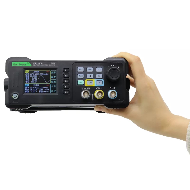
The appearance of the ET3320C
The first thing you notice when you take the ET3320C out of its packaging is its amazingly low weight of just 552 grams and its equally amazingly small dimensions of 19.5 cm x 8.5 cm x 18.5 cm. The first one is a consequence of the fact that this generator is housed in a case made entirely of plastic, in which not a milligram of metal can be detected. The second one results in the fact that the control knobs and the three BNC connectors are, at least to our feeling, a bit too close together for easy operation of the device.
The display is also small, measuring just 48 mm by 36 mm. Nevertheless, this tiny display features ten lines of text summarising the specifications of the two output signals. Two? Yes, because the ET3320C contains two identical function generators whose output signals you can set completely individually. In addition, you can also use the device as a frequency meter, specifying a frequency range of up to 100 MHz.
As you can see in the picture below, the ET3320C has a bracket that you can click into various positions, but can also hide completely under the case if desired.
 |
The very small function generator ET3320C. (© 2023 Banggood) |
Price and scope of delivery
The ET3320C is the cheapest device in the series. You will pay between € 100.00 and € 130.00 for this type at the well-known internet sources such as Banggood and AliExpress affiliated suppliers. With its frequency range of up to 20 MHz, this generator offers even more than the average hobbyist needs.
In addition to the function generator, three BNC cables are supplied. A USB cable is intended to connect the generator to your PC. However, the necessary software is not yet available at the time of writing this article. Please note that a mains cable is missing, so you will need to purchase it additionally.
 |
| The cables supplied with the ET3320C. (© 2023 Banggood) |
The manual
In the box is an A5 booklet of 16 pages where the operation of the device is described rather compact in good English. We have scanned this manual and posted it on our account on archive.org:
➡ Browse the manual
The back of the device
On the back panel, there is a type-B USB connector for connecting to a PC, a small ten-pin connector for serial communication and an IEC C13 male connector for the mains cable. Below this connector is a small toggle switch for switching the mains power on and off. Note that there is no fuse holder! The grid suggests that there is a fan inside, but this is not the case. It is likely that this case with this back panel is used for several devices.
 |
| The back of the ET3320C. (© 2023 Banggood) |
The front panel of the device
Next to the display are five push buttons 'F1' to 'F5'. These are the so-called 'soft keys' whose function depends on the mode the generator is in. This function is described on the display. For example, you can use them to select the waveform or to select one of the following output signal parameters:
- Frequency.
- Amplitude.
- Offset.
- Duty cycle.
- Phase.
Afterwards, you can use the arrow keys and the rotary knob to set the value of the selected parameter to the desired value.
The keypad contains nine keys:
The large rotary knob next to the keypad allows you to adjust the value of function or digit selected with the keys.
At the bottom left is a small round button that allows you to switch the ET3320C on and off. If you switch the generator off with this, the mains voltage remains however present and therefore the electronics remain energised. To remind you of this, this button lights up briefly every four seconds.
The display
The figure below shows the display. It consists of three frames. The right-hand frame shows the function of the five softkeys. The key that is active is shown in yellow. The two left-hand frames show the parameters of the two output signals. Yellow represents channel 1, light blue represents channel 2. The largest frame indicates the channel in which you can set the parameters of the output signal.
Next to the display are five push buttons 'F1' to 'F5'. These are the so-called 'soft keys' whose function depends on the mode the generator is in. This function is described on the display. For example, you can use them to select the waveform or to select one of the following output signal parameters:
- Frequency.
- Amplitude.
- Offset.
- Duty cycle.
- Phase.
Afterwards, you can use the arrow keys and the rotary knob to set the value of the selected parameter to the desired value.
The keypad contains nine keys:
- WAVE:
Selection of the desired signal shape: sine, rectangle, triangle, pulse ore 32 random signal shapes stored in memory. - MOD:
Selection of the modulation of the output signal: pulse modulation, linear sweep, logarithmic sweep, burst modulation, amplitude modulation (AM), frequency modulation (FM), phase modulation, amplitude shift modulation (ASK), frequency shift modulation (FSK). - SYS:
System settings, such as save and load output signal programming, display intensity, beep sound, language and factory reset. - MEAS:
Using the external input to measure frequencies or number of pulses. - ← →:
Use these keys to select the digit in the display that you want to set to a certain value with the rotary knob. - OK:
Turn both output voltages on or off. - CH1:
Selects channel 1 for setting the signal parameters. - CH2:
Selects channel 2 for setting the signal parameters.
The large rotary knob next to the keypad allows you to adjust the value of function or digit selected with the keys.
At the bottom left is a small round button that allows you to switch the ET3320C on and off. If you switch the generator off with this, the mains voltage remains however present and therefore the electronics remain energised. To remind you of this, this button lights up briefly every four seconds.
 |
| The front panel of the ET3320C. (© 2023 AliExpress) |
The display
The figure below shows the display. It consists of three frames. The right-hand frame shows the function of the five softkeys. The key that is active is shown in yellow. The two left-hand frames show the parameters of the two output signals. Yellow represents channel 1, light blue represents channel 2. The largest frame indicates the channel in which you can set the parameters of the output signal.
So in the example given, channel 'CH1' is adjustable, the amplitude setting is activated and the user has selected the third digit of the amplitude setting using the arrow keys. Indeed, this digit is framed in red. Using the rotary knob, it is now possible to vary the numerical value of this digit.
Pay attention to the rather unclear way in which the frequency is displayed. Since the resolution of this setting is 1 μHz, the frequency must be displayed with fourteen digits! For some obscure reason, the European decimal point is not represented by the Anglo-Saxon comma, but by an accent! Our decimal comma is represented by the Anglo-Saxon decimal point. We had to get used to this notation! So in the example in the picture below, the frequency is set to 00,010,000.000,000 Hz, or 10 kHz.
 |
| The display of the ET3320C. (© 2023 Jos Verstraten) |
The specifications of the ET3320C
- Number of channels: 2
- Phase synchronisation: between both channels possible
- Sine frequency range: 1 μHz ~ 20 MHz
- Rectangle frequency range: 1 μHz ~ 15 MHz
- Triangle frequency range: 1 μHz ~ 15 MHz
- Pulse frequency range: 100 μHz ~ 6 MHz
- Arbitrary waveform frequency range: 1 μHz ~ 6 MHz
- Frequency resolution: 1 μHz
- Frequency accuracy: ±20 ppm
- Frequency stability: ±1 ppm/3 hours
- Waveform description: 8,192 samples
- Waveform resolution: 13 bit
- Sampling rate: 200 MSamples/s
- Output voltage: 2 mVpeak-to-peak ~ 20 Vpeak-to-peak to 10 MHz sine wave
- Output voltage: 2 mVpeak-to-peak ~ 10 Vpeak-to-peak to 20 MHz sine wave
- Output voltage resolution: 1 mV
- Output voltage accuracy: 1 % of set value ±1 mV
- Offset voltage range: -9.99 V ~ +9.99 V
- Duty cycle range: 0.2 % ~ 99.8 %
- Phase shift range: 0° ~ 359.9°
- Harmonic distortion on sine: less than 0.8 % up to 20 kHz
- Amplitude flatness on sine: ±0.4 dB up to 10 MHz
- Amplitude flatness on sine: ±1.0 dB up to 20 MHz
- Rise and fall time rectangle: less than 20 ns
- Overshoot on rectangle: less than 5 %
- Jitter on rectangle and pulse: 6 ns maximum
- Saw-tooth linearity: greater than 98 % up to 10 kHz
- Pulse width: 20 ns minimum
- Output impedance: 2 x 50 Ω
- Output protection: 60 second short-circuit proof
- Frequency measurement range: 100 MHz
- Pulse measurement range: 4294967295
- Frequency and pulse meter input voltage: 20 Vpeak-to-peak maximum
- Waveform storage: 100
- Modulation: internal ~ external
- Display: 2.4 inch 320 x 240 TFT
- Mains voltage: 100 Vac ~ 240 Vac
- Power consumption: less than 15 W
- Interface language: English ~ Chinese
Opening the case
You must first remove the bracket. Fortunately, there is one position where you can pull this bracket out of the case without any problems. The front and back panels simply snap into the top and bottom of the case. You can use a screwdriver to wiggle briefly under the centre of the panels to loosen these panels. On the bottom of the case there is a type sticker in the middle. If you remove it, you will see a single screw underneath that connects the two parts of the case. After removing this rather long screw, you can carefully take apart the function generator.
- Phase synchronisation: between both channels possible
- Sine frequency range: 1 μHz ~ 20 MHz
- Rectangle frequency range: 1 μHz ~ 15 MHz
- Triangle frequency range: 1 μHz ~ 15 MHz
- Pulse frequency range: 100 μHz ~ 6 MHz
- Arbitrary waveform frequency range: 1 μHz ~ 6 MHz
- Frequency resolution: 1 μHz
- Frequency accuracy: ±20 ppm
- Frequency stability: ±1 ppm/3 hours
- Waveform description: 8,192 samples
- Waveform resolution: 13 bit
- Sampling rate: 200 MSamples/s
- Output voltage: 2 mVpeak-to-peak ~ 20 Vpeak-to-peak to 10 MHz sine wave
- Output voltage: 2 mVpeak-to-peak ~ 10 Vpeak-to-peak to 20 MHz sine wave
- Output voltage resolution: 1 mV
- Output voltage accuracy: 1 % of set value ±1 mV
- Offset voltage range: -9.99 V ~ +9.99 V
- Duty cycle range: 0.2 % ~ 99.8 %
- Phase shift range: 0° ~ 359.9°
- Harmonic distortion on sine: less than 0.8 % up to 20 kHz
- Amplitude flatness on sine: ±0.4 dB up to 10 MHz
- Amplitude flatness on sine: ±1.0 dB up to 20 MHz
- Rise and fall time rectangle: less than 20 ns
- Overshoot on rectangle: less than 5 %
- Jitter on rectangle and pulse: 6 ns maximum
- Saw-tooth linearity: greater than 98 % up to 10 kHz
- Pulse width: 20 ns minimum
- Output impedance: 2 x 50 Ω
- Output protection: 60 second short-circuit proof
- Frequency measurement range: 100 MHz
- Pulse measurement range: 4294967295
- Frequency and pulse meter input voltage: 20 Vpeak-to-peak maximum
- Waveform storage: 100
- Modulation: internal ~ external
- Display: 2.4 inch 320 x 240 TFT
- Mains voltage: 100 Vac ~ 240 Vac
- Power consumption: less than 15 W
- Interface language: English ~ Chinese
The interior of the ET3320C
Opening the case
You must first remove the bracket. Fortunately, there is one position where you can pull this bracket out of the case without any problems. The front and back panels simply snap into the top and bottom of the case. You can use a screwdriver to wiggle briefly under the centre of the panels to loosen these panels. On the bottom of the case there is a type sticker in the middle. If you remove it, you will see a single screw underneath that connects the two parts of the case. After removing this rather long screw, you can carefully take apart the function generator.
 |
| The electronics in the ET3320C. (© 2023 Jos Verstraten) |
The main PCB
Screwed to the bottom of the case is an amazingly small PCB, which nevertheless houses almost all of the ET332C's electronics. At the very bottom left, you can see the connector to which the two wires of the mains switch are connected. The mains voltage goes to a small PCB soldered perpendicular to the main PCB. This is where the 230 V is converted into a DC voltage. Here too, however, a fuse is missing!
It is very easy to see how the PCB is split into two parts. The lower part is responsible for producing the supply voltages for all circuits. There are PCB symbols referring to voltages of +12 V, +15 V, -15 V, +5 Vanalogue, +5 Vdigital, +2.7 V and -2.7 V.
At the heart of the ET3320C is a Pango PGL12G. That is a 'Field Programmable Gate Array' (FPGA) from Alinx. In this one very large-scale IC, almost all the digital hardware present in this device is programmed. On the top right is the analogue part of the circuit, specifically the output amplifiers and attenuators. For the analogue output amplifiers, two pieces of LM7171 are used. These are 'Very High Speed Current/Voltage Feedback Amplifiers' with a slew rate of no less than 4,100 V/μs. The eight yellow parts are relays used in the voltage divider for setting the magnitude of the output voltage. For example, you can hear those relays switch on and off at the transition to over 10 V, over 5 V, over 2.5 V and over 1.25 V output voltage. An LM358 dual op-amp is also present in this analogue section.
 |
| The main PCB of the ET3320C. (© 2023 Jos Verstraten) |
A PCB with bugs?
It is worth noting that in the lower left corner of the PCB, some repair work has been soldered by hand. We have enlarged this part of the PCB in the photo below. So have we received a device from the pre-production phase?
 |
| The delicious old-fashioned handwork...... (© 2023 Jos Verstraten) |
The AC/DC power supply PCB
The picture below shows what is present on the small PCB soldered to the main PCB. You will recognise the components familiar from such switched-mode power supplies as HF transformers and electrolytics. But again, there is no fuse to be discovered!
The manufacturer of this device does not find it necessary to fit an easily replaceable fuse, e.g. in a fuse holder on the back, in the primary power supply circuit! We find this a serious violation of the basic rules of good design!
 |
| The small power supply PCB. (© 2023 Jos Verstraten) |
The standby power consumption
If you use the ET3320C standing freely on the table, you can easily switch the generator on and off with the 230 V mains switch on the back. This is different if you build the unit into a 'measuring device wall' on a rack above your work desk. You will then always leave the primary mains switch in the on position and activate the generator with the push button in the bottom left corner. This means that the circuit is always consuming power. We measured this standby consumption by inserting an old analogue AVO meter into the 230 V circuit in the AC position. In the 'switched off' state, we measured a current of 11 mA. At a mains voltage of 230 V, this therefore corresponds to an average standby power consumption of about 2.5 W.
A serious point of criticism
The three BNC connectors are soldered directly to the PCB. This is nice and cheap because it saves the manufacturer a lot of assembly and soldering work. However, the shield of these connectors is electrically connected to the earthed contact of the mains plug. That connection is made via a large copper plane on the PCB, which forms the circuit's ground. Somewhere on the PCB, a solder tab under a screw makes contact with this ground plane. A wire is soldered to this solder lug, which goes to the earth of the male connector for the mains cable.
This works perfectly well in normal operation of the function generator. But now suppose you make a serious mistake when connecting the generator to a circuit, accidentally connecting the earth of the BNC connector to the mains phase. Then a short circuit occurs. The large short-circuit current flows through the PCB to the mains cable earth. We consider the chances of the PCB surviving such an incident quite small!
An introductory note on voltage levels
You can set the signal voltage between 2 mV and 20 V. However, the ET3320C works with the peak-to-peak value of the signal. This is a problem when setting a sine wave voltage. After all, we are used to indicating the voltage of a sine wave by its rms value! Function generators of the more expensive kind have that possibility built in, the ET3320C does not. If you want to set the rms value of a sine wave, use the conversion factor below:
Vpeak-to-peak = Vrms x 2.82
Suppose you need a sine wave voltage of 0.775 V (0 dBm), you need to set the ET3320C to a voltage of 2.185 V.
Setting the fundamental functions
In most cases, you use a function generator to generate a signal with a signal shape, a signal frequency and a signal magnitude. Suppose you want to set channel 1 to a sine wave voltage of 1.0 Vrms and with a frequency of 10 kHz. You must then perform the following operations:
Setting the modulation
The ET3320C offers a lot of possibilities to modulate the output signal, both with an internal and an external signal. You connect the external signal to the 'Ext.IN' connector, of course. All those settings come into view after pressing the 'MOD' button. In the top frame 'ModuMode', you can use the rotary knob or 'F1' (FUNC) to set the modulation to:
- Pulse Wave (PLS)
- Sweep Frequency (SF)
- Burst (BST)
- Amplitude Modulation (AM)
- Frequency Modulation (FM)
- Phase Modulation (PM)
- Amplitude Shift Key (ASK)
- Frequency Shift Key (FSK)
- Phase Shift Key (PSK)
and this, of course, for both channels separately.
In the bottom box, you can see which settings are present with the 'F' keys for each modulation type. In the picture below, for example, you can see the options provided for amplitude modulation. With the 'F2' and 'F3' keys you select one of the options, with the rotary knob you set that option. With 'F5' (Ctrl) you set the defined modulation on the output connector. 'F4' (Wave) exits the generator's modulation option.
If you use the ET3320C standing freely on the table, you can easily switch the generator on and off with the 230 V mains switch on the back. This is different if you build the unit into a 'measuring device wall' on a rack above your work desk. You will then always leave the primary mains switch in the on position and activate the generator with the push button in the bottom left corner. This means that the circuit is always consuming power. We measured this standby consumption by inserting an old analogue AVO meter into the 230 V circuit in the AC position. In the 'switched off' state, we measured a current of 11 mA. At a mains voltage of 230 V, this therefore corresponds to an average standby power consumption of about 2.5 W.
A serious point of criticism
The three BNC connectors are soldered directly to the PCB. This is nice and cheap because it saves the manufacturer a lot of assembly and soldering work. However, the shield of these connectors is electrically connected to the earthed contact of the mains plug. That connection is made via a large copper plane on the PCB, which forms the circuit's ground. Somewhere on the PCB, a solder tab under a screw makes contact with this ground plane. A wire is soldered to this solder lug, which goes to the earth of the male connector for the mains cable.
This works perfectly well in normal operation of the function generator. But now suppose you make a serious mistake when connecting the generator to a circuit, accidentally connecting the earth of the BNC connector to the mains phase. Then a short circuit occurs. The large short-circuit current flows through the PCB to the mains cable earth. We consider the chances of the PCB surviving such an incident quite small!
Working with the ET3320C
An introductory note on voltage levels
You can set the signal voltage between 2 mV and 20 V. However, the ET3320C works with the peak-to-peak value of the signal. This is a problem when setting a sine wave voltage. After all, we are used to indicating the voltage of a sine wave by its rms value! Function generators of the more expensive kind have that possibility built in, the ET3320C does not. If you want to set the rms value of a sine wave, use the conversion factor below:
Vpeak-to-peak = Vrms x 2.82
Suppose you need a sine wave voltage of 0.775 V (0 dBm), you need to set the ET3320C to a voltage of 2.185 V.
Setting the fundamental functions
In most cases, you use a function generator to generate a signal with a signal shape, a signal frequency and a signal magnitude. Suppose you want to set channel 1 to a sine wave voltage of 1.0 Vrms and with a frequency of 10 kHz. You must then perform the following operations:
- Press the 'CH1' button, the yellow frame of CH1 is displayed enlarged.
- Press the 'WAVE' key, with the five function keys you can now select one of the five available waveforms, see the figure below. Press 'F1', the sine waveform is selected.
- After selecting the waveform, the function keys immediately regain the basic functions that allow you to define the parameters of the sine wave.
- Press 'F1', the left digit of the frequency turns red.
- Use the arrow keys to move to the digit representing kHz, see the picture below, and turn the round button until the frequency equals 10 kHz.
- Press 'F2', The left digit of the amplitude turns red.
- Using the arrow keys, select the digits one after another and use the rotary knob to set it to 02.820 V.
- You can leave the offset, duty cycle and phase at 0.00 V, 50.0 % and 000.0° respectively.
 |
| Setting a channel to the desired output voltage. (© 2023 Jos Verstraten) |
Setting the modulation
The ET3320C offers a lot of possibilities to modulate the output signal, both with an internal and an external signal. You connect the external signal to the 'Ext.IN' connector, of course. All those settings come into view after pressing the 'MOD' button. In the top frame 'ModuMode', you can use the rotary knob or 'F1' (FUNC) to set the modulation to:
- Pulse Wave (PLS)
- Sweep Frequency (SF)
- Burst (BST)
- Amplitude Modulation (AM)
- Frequency Modulation (FM)
- Phase Modulation (PM)
- Amplitude Shift Key (ASK)
- Frequency Shift Key (FSK)
- Phase Shift Key (PSK)
and this, of course, for both channels separately.
In the bottom box, you can see which settings are present with the 'F' keys for each modulation type. In the picture below, for example, you can see the options provided for amplitude modulation. With the 'F2' and 'F3' keys you select one of the options, with the rotary knob you set that option. With 'F5' (Ctrl) you set the defined modulation on the output connector. 'F4' (Wave) exits the generator's modulation option.
 |
| The display after selecting amplitude modulation. (© 2023 Jos Verstraten) |
'Sweep Frequency' option
Quickly sweep through a certain frequency range is a useful option to get an idea about the frequency range of an audio circuit. The creators of the ET3320C's software have placed this function in the modulation settings. A rather strange decision, because with most function generators one considers the sweep function to be something separate from the modulation options anyway. Because the ET3320C has a lot to offer in this area too, we pay a little extra attention to it. The picture below shows the display after selecting the ModuMode 'Sweep Frequency'.
You can set:
You can set:
- Type:
Linear increasing Frequency.
Linear decreasing frequency.
Linear increasing and then decreasing frequency.
Logarithmic increasing frequency.
Logarithmic decreasing frequency.
Logarithmic increasing and then decreasing frequency. - Source:
Internal
External AC
External DC
Manual - Time:
Here you can set the time of a sweep between 1 ms and 999,999 s. - Start and End:
Set the start and end frequencies of the sweep.
 |
| Sweeping the output signal. (© 2023 Jos Verstraten) |
The 'SysSetup'
After pressing the 'SYS' key, the screen below will open where you can save some seldom to vary settings.
- Save&Load:
You can store no less than one hundred programming settings of both channels in the device's memory and activate them afterwards. - Sound:
Turns on or off the beeping of the generator after each operation. - Brightness:
Adjusts the intensity of the display in ten steps. - Language:
Selects Chinese or English as the display language. - Arb Wave:
Selects one of the fifty irregular signal shapes stored in memory.
 |
| 'SysSetup' options. (© 2023 Jos Verstraten) |
The frequency and pulse meter
After pressing the 'MEAS' key, your function generator transforms into a digital frequency and pulse meter, see the 'MeasMode' display below.
- FUNC:
Selects between 'Counter' and 'Freq Meter'. - COUP:
Selects between 'AC' and 'DC'. - GATE:
Allows you to set the measurement time between 10.00 s and 00.01 s.
 |
| 'MeasMode' options. (© 2023 Jos Verstraten) |
The ET3320C from 'East Tester' tested
Introduction
Of a device with as many capabilities as this function generator, one can test dozens of specifications and functions and check whether they meet the specifications. In the following paragraphs, we give the results of a few tests which, we hope, will give you a good understanding of the capabilities and impossibilities of this function generator.

The amplitude flatness of the output voltage at sine wave
Since we do not have an AC voltmeter that measures up to 20 MHz, we have to determine the flatness of the amplitude as a function of frequency with our oscilloscope. This XDS2102A from OWON has a bandwidth of 100 MHz. We first measured a signal of 1 kHz and about 1.5 V and set the horizontal cursors at the peaks of this signal. Afterwards, we increased the frequency of the ET3320C. Below, you can see the results at 1 MHz, 5 MHz, 10 MHz and 20 MHz. At 10 MHz, the peak-to-peak value dropped to 87.6% of the value at 1 kHz. At 20 MHz, this drop is 68.9 %, although at this frequency the attenuation of our oscilloscope probably also starts to play a role.
 |
| The amplitude flatness of the output voltage as a function of frequency. (© 2023 Jos Verstraten) |
Output voltage accuracy at sine wave
As our next test on the sinusoidal output signal, we measured the accuracy of the peak-to-peak value setting. We used our ET3255 as a reference meter and to make sure that it achieves its specified accuracy of ±0.3%, we set the measurement frequency to a safe 1 kHz. The results are summarised in the table below.
 |
| Voltage accuracy at sine wave output. (© 2023 Jos Verstraten) |
The signal shape of the sine wave at 20 MHz
If you do not make the voltage too large, the ET3320C delivers an apparently good sine wave form up to the very highest frequency of 20 MHz. However, at voltages higher than 1 Vrms, you will see that the fast large signal variations in the edges cannot be followed by the analogue electronics and distortions occur. This is why the manufacturer limits the maximum voltage at frequencies above 10 MHz to 10 V.
 |
| The 20 MHz sine wave form at 1.0 Vrms and at 3.0 Vrms. (© 2023 Jos Verstraten) |
Digital noise on the sine wave at low voltages
Almost all digital function generators produce digital noise on the output voltage. This is the result of the imperfect digital-to-analogue conversion. If you set a large signal, this is not such a problem. However, the noise becomes annoying if you set the amplitude of the generator to a very small voltage. We set the generator to the smallest voltage possible: 2 mV at 1 kHz. The result is impressive, see the oscillogram below. Very little digital noise! To assess the oscilloscope's own noise, we set the second channel to the same sensitivity of 1 mV/div. This input is connected with an identical BNC cable to a 50 Ω terminator. Thus, the vast majority of the noise present on the signal comes from the oscilloscope and wiring and not from the ET3320C!
 |
| Digital noise on a small sine wave voltage. (© 2023 Jos Verstraten) |
The total harmonic distortion on the sine wave
This parameter is specified as less than 0.8 % up to 20 kHz. With our distortion analyser 331A from Hewlett Packard, we measure a lowest value of only 0.09 % at 10 kHz and a signal of 10 Vpeak-to-peak! As the oscillogram below shows, this distortion consists mainly of the second harmonic.
 |
| Harmonic distortion at 10 kHz. (© 2023 Jos Verstraten) |
The rectangle voltage output
Since the bandwidth of our 100 MHz oscilloscope is too small to objectively assess the display of a 10 MHz rectangle, we compare the display with that of our pulse generator PM5704. This delivers very steep TTL pulses. Of course, we use 50 Ω terminators on both oscilloscope inputs. The oscillograms below show the representation of a 1 MHz and a 10 MHz square wave. The yellow traces are those of the ET3320C, the blue of the PM5704.
 |
| Display of 1 MHz and 10 MHz square waves. (© 2023 Jos Verstraten) |
Detailed view of the rise time
We measured this parameter at 1 MHz, again using the PM5704's steep pulse as a reference (blue trace). Both signals are of course terminated again with 50 Ω terminators.
AM and FM examples
In the figure below, we have collected the results of two modulation settings. The left one gives 50% amplitude modulation with a 1 kHz signal on a 20 kHz carrier. The right one gives a 20 kHz carrier modulated in frequency with a deviation of 10 kHz.
An example of burst modulation
What kind of output signals you can generate by using burst modulation follows from the oscillogram below. You can use such signals to assess, for example, the maximum power output of an amplifier. Of course, the number of periods of the burst is adjustable.
Offset limits
The offset function allows you to superimpose the signal supplied by the generator on an adjustable positive or negative DC voltage. According to the specifications, you can set up to a maximum of +9.99 V or -9.99 V offset. However, if you are working with a large output signal, the output voltage will become distorted against one of the internal supply voltages if you add too much offset to the signal. Using the oscillogram below, we have determined the limits of the maximum offset. These are approximately -2.30 V and +3.10 V at maximum Ampl setting.
The linearity of the triangle
This is excellent, see the oscillogram below showing the rising edge of a triangle at a frequency of 1 MHz. Even around zero, where most bits of the DAC should suddenly change value, no irregularity can be detected in the signal.
The frequency meter tested
The frequency meter in the ET3320C turns out to be very insensitive! For a sine signal with a frequency of 1 kHz, we have to turn up the signal to 1.5 Vrms before the generator gives a stable reading. Above 10 MHz, sensitivity even drops to 1.9 Vrms. However, the accuracy does turn out to be excellent. For a reference signal with a frequency of 10.000,0 MHz, the ET3320C gives a value of 10.000,018,990 MHz.
Very annoying, however, is the fact that the readout remains at the last measured value if you remove the signal from the 'Ext.IN' connector. So the readout does not jump to zero, which would be expected. Only reconnecting a signal of sufficient amplitude causes the device to replace the old readout with the new measurement.
We have worked with about five function generators in the price range around € 100.00 over the past three years. So we can do a bit of comparison. The ET3320C comes out of this comparison as the best and most versatile function generator without any reservations. With this device, 'East Tester' has set a new standard on the market! We can unreservedly recommend this function generator to any serious hobbyist who wants to buy a good and versatile function generator for not too much money.
The only two points of criticism, but immediately very serious ones, are the lack of a fuse in the primary supply circuit and the fact that the ground of the three BNC connectors is connected to the mains plug ground only via the PCB.

(Banggood sponsor ad)
ET3320C function generator
We measured this parameter at 1 MHz, again using the PM5704's steep pulse as a reference (blue trace). Both signals are of course terminated again with 50 Ω terminators.
 |
| Detailed view of the rise time at 1 MHz. (© 2023 Jos Verstraten) |
AM and FM examples
In the figure below, we have collected the results of two modulation settings. The left one gives 50% amplitude modulation with a 1 kHz signal on a 20 kHz carrier. The right one gives a 20 kHz carrier modulated in frequency with a deviation of 10 kHz.
 |
| Examples of AM and FM signals. (© 2023 Jos Verstraten) |
An example of burst modulation
What kind of output signals you can generate by using burst modulation follows from the oscillogram below. You can use such signals to assess, for example, the maximum power output of an amplifier. Of course, the number of periods of the burst is adjustable.
 |
| Example of burst modulation. (© 2023 Jos Verstraten) |
Offset limits
The offset function allows you to superimpose the signal supplied by the generator on an adjustable positive or negative DC voltage. According to the specifications, you can set up to a maximum of +9.99 V or -9.99 V offset. However, if you are working with a large output signal, the output voltage will become distorted against one of the internal supply voltages if you add too much offset to the signal. Using the oscillogram below, we have determined the limits of the maximum offset. These are approximately -2.30 V and +3.10 V at maximum Ampl setting.
 |
| Signal distortion due to too much offset. (© 2023 Jos Verstraten) |
The linearity of the triangle
This is excellent, see the oscillogram below showing the rising edge of a triangle at a frequency of 1 MHz. Even around zero, where most bits of the DAC should suddenly change value, no irregularity can be detected in the signal.
 |
The linearity of the triangle at 1 MHz. |
The frequency meter tested
The frequency meter in the ET3320C turns out to be very insensitive! For a sine signal with a frequency of 1 kHz, we have to turn up the signal to 1.5 Vrms before the generator gives a stable reading. Above 10 MHz, sensitivity even drops to 1.9 Vrms. However, the accuracy does turn out to be excellent. For a reference signal with a frequency of 10.000,0 MHz, the ET3320C gives a value of 10.000,018,990 MHz.
Very annoying, however, is the fact that the readout remains at the last measured value if you remove the signal from the 'Ext.IN' connector. So the readout does not jump to zero, which would be expected. Only reconnecting a signal of sufficient amplitude causes the device to replace the old readout with the new measurement.
Our verdict on the ET3320C from 'East Tester'
We have worked with about five function generators in the price range around € 100.00 over the past three years. So we can do a bit of comparison. The ET3320C comes out of this comparison as the best and most versatile function generator without any reservations. With this device, 'East Tester' has set a new standard on the market! We can unreservedly recommend this function generator to any serious hobbyist who wants to buy a good and versatile function generator for not too much money.
The only two points of criticism, but immediately very serious ones, are the lack of a fuse in the primary supply circuit and the fact that the ground of the three BNC connectors is connected to the mains plug ground only via the PCB.
ET3320C function generator