|
Googling for interesting stuff, we found this inexpensive kit of a frequency, capacitor and coil meter for just €15.00 from various AliExpress providers. That obviously deserves a test! |
Introduction to this f-L-C meter kit
Nameless and unbranded
Chinese suppliers have a habit of hiding the manufacturer of products very well. This little kit really takes the cake in this respect. We cannot find a manufacturer or even a type number. If you want to buy it, you can google 'LCD Digital Secohmmeter Frequency Capacitance Inductance Meter Cymometer CF Inductor Capacitor Tester Permittimeter DIY Kit' and you will find a number of providers. Direct links to providers on AliExpress that have this DIY kit in their programme at the time of writing this test:
➡ https://nl.aliexpress.com/item/1005004353851383.html
➡ https://nl.aliexpress.com/item/1005002318108128.html
➡ https://nl.aliexpress.com/item/1005001570560540.html
The kit is offered, including shipping, at a price of around €15.00. As you can notice, there are two different PCB layouts in circulation.
What can this f-L-C meter kit do?
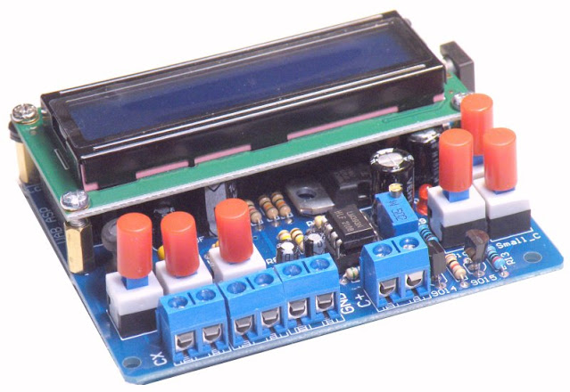
According to the suppliers, you can use this kit to measure the value of 'normal' capacitors, electrolytics and coils, and you can measure the frequency of an AC voltage signal on the display. As shown in the photo below, the electronics are housed on a small main PCB on which you plug the well-known LCD1602 display PCB.
There are six push buttons on the main PCB that you use to select one of the four measurement modes. There are four measurement inputs present in the form of PCB terminal blocks. You have to use a different input for each type of measurement. All a bit primitive, but of course you cannot demand luxury for a price of just €15.00!
 |
| The completely built f-L-C meter. (© 2023 Jos Verstraten) |
The technical specifications
According to the vendors, this little kit has the following specifications:
- Display: LCD, model LCD1602 with illumination
- Power supply DC: 8 Vdc ~ 14 Vdc
- Power supply AC: 7 Vac ~ 10 Vac
- Measuring range coils: 0.1 μH ~ 1 H
- Resolution coils measurement: 0.1 μH
- Measuring range 'normal' capacitors: 1 pF ~ 2.2 μF
- Resolution capacitor measurement: 1 pF
- Electrolytic capacitors measuring range: 0.50 μF ~ 12,000 μF
- Resolution electrolytic capacitor measurement: 0.01 μF
- Measuring range frequency: 20 Hz ~ 400 kHz
- Resolution frequency measurement: 1 Hz
- Dimensions main PCB: 80 mm x 70 mm
- Weight: 90 g
Delivery of the kit
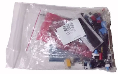
This is delivered, in familiar Chinese style, in a far too small plastic bag stuffed back into an envelope. The microcontroller is attached, along with its socket, to a piece of styrofoam (!).
This is delivered, in familiar Chinese style, in a far too small plastic bag stuffed back into an envelope. The microcontroller is attached, along with its socket, to a piece of styrofoam (!).
 |
| The delivery of the kit. (© 2023 Jos Verstraten) |
The building instructions
This is unfortunately not included. Even after an intense search on the internet, we cannot find it. Some absolutely necessary instructions, such as what the function of the two supplied adjustment potentiometers is and how they should be adjusted, we fortunately found on a Russian sales site for this kit. We will come back to this in the course of this story.

The components supplied
In the picture below, you can see what you get for your € 15.00. All components are 'old-fashioned' axial or radial, no SMDs are used. Sockets are supplied for the two ICs. For attaching the display PCB to the main PCB, four brass spacers are provided and only four bolts. In fact, there should be eight and you will also need some spacers, which are also not supplied.
 |
| The components of this kit. (© 2023 Jos Verstraten) |
The main PCB
The picture below shows the two sides of the main PCB. It is of excellent quality. Because the silkscreen indicates the value of each component, you can still, even without the manual, completely solder the PCB.
 |
| The two sides of the main PCB. (© 2023 Jos Verstraten) |
The electronics of this kit
The complete circuit diagram
After some searching on the internet, we found the schematic of this kit. We have presented it, slightly edited, in the figure below.
Via connector J4, you connect the power supply to the board. This leads to a bridge rectifier D1, D2, D4, D5 and from there to U2, an LM7805 stabiliser. Switch S4 is the ON/OFF switch, it switches the +5 V to the rest of the circuit on or off.
J9 is a PCB connector on the main PCB to which you connect the display board. The adjustment potentiometer R10 controls the brightness of the LCD display LCD1602.
The microcontroller of type AT89S52 is clocked with a crystal Y1 of 12 MHz.
How the circuit is capable of measuring frequencies, capacitances and inductances is, in the absence of documentation on the schematic, not clear. When measuring 'normal' capacitors, the input J5 carries a sort of sine wave voltage with a frequency of about 378 kHz and an rms value of about 10 mV. When connecting a capacitor to be measured, both the frequency and value of this signal become smaller. Where this signal comes from, however, cannot be understood by us. Perhaps one of our readers can figure out how this circuit works?
Clearly, the five pushbutton switches that determine which measurement function is selected ground one of the microcontroller's P inputs. This probably tells the microcontroller which measurement mode is selected. The two comparators in the LM393 must have something to do with converting the analogue signals over the parts being measured into digital signals for the microcontroller.
The adjustment potentiometer R16 is in the part of the circuit that measures electrolytics and is intended to adjust this measurement function. This part of the circuit has two options, namely 'small electrolytic capacitors' and 'large electrolytic capacitors'. The switchover point is at 1,000 μF. When measuring smaller electrolytics, you need to press switch S6, for larger electrolytics S7.
 |
| The schematic of this kit. (© 2023 Jos Verstraten) |
Building the kit
Soldering the main PCB
- Start by soldering the sixteen resistors:
- 1 x 100 Ω
- 5 x 1 kΩ
- 3 x 2 kΩ
- 1 x 5.6 kΩ
- 2 x 10 kΩ
- 1 x 47 kΩ
- 3 x 100 kΩ
- Then solder the five diodes:
- 4 x 1N4007
- 1 x LED (D13), the long connecting wire is the plus
- Mount the resistor network A09-103 under the large IC socket of U1
- Then come the two IC sockets for U1 and U3
- Solder the five capacitors:
- 2 x 22 pF (code 22)
- 2 x 1 nF (code 102)
- 1 x 1,000 nF (code 105)
- Solder the crystal (code 12,000)
- Solder the two transistors:
- Q1 (code S9015)
- Q2 (code S9014)
- Solder the seven electrolytics, the shaded part is the min:
- 4 x 10 μF
- 3 x 470 μF
- Note that C6, under the IC base, should lie flat on the PCB. The three 470 μF electrolytics should be pushed onto the PCB as deeply as possible, because if they are soldered slightly too high on the PCB, the display PCB will no longer fit on the main PCB
- Mount the coil L1 of 100 μH
- Now the LM7805 (U2), you need to bend the connecting wires 90° so that the stabiliser lies flat on the PCB
- The adjustment potentiometer R10 of 10 kΩ
- The adjustment potentiometer R16, note the position of the screw!
- The 16-pin PCB connector J9
- The 10-pin UAB_ASP connector
- The four PCB terminal blocks
- The power connector
- The six push buttons
- Screw the four spacers onto the PCB
- Mount the two ICs, paying attention to their position.
The picture below shows the completely soldered PCB.
 |
| The completely soldered main PCB. (© 2023 Jos Verstraten) |
Mounting the display board
From the strip of PCB header, cut a piece with sixteen pins and push it with the long pins into the sixteen-pole PCB connector J9. Mount the display PCB with four additional screws and four plastic spacer washers on the four spacer sockets. The spacers are necessary because the electrolytic capacitors C1 and C3 are slightly higher than the spacers. The sixteen short pins of the PCB header now just stick through the display PCB and you can solder them onto the PCB.
The photo below shows the end result, but the display board has not yet been soldered onto the main PCB.
 |
| The final result of the assembly. (© 2023 Jos Verstraten) |
The f-L-C meter kit tested
Adjusting the display
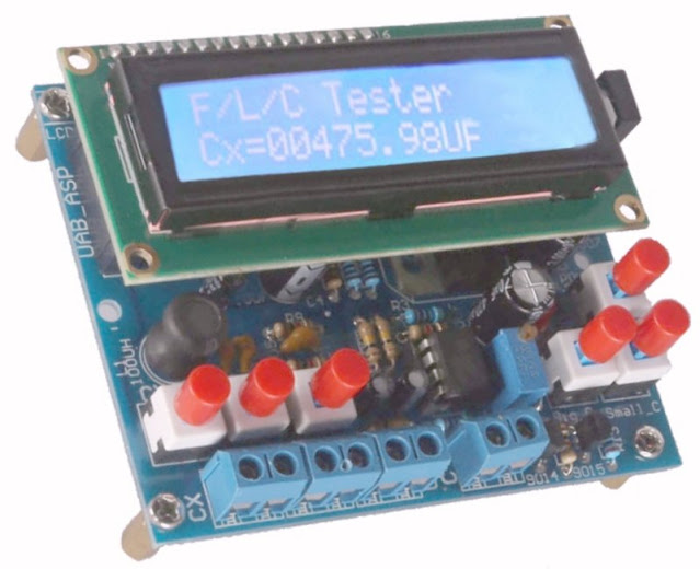
After connecting the power supply and switching on the little device, chances are you will see nothing at all on the display. Don't panic! By turning the adjustment potentiometer R10, on the back of the PCB, you can make the welcome text below visible on the display.
 |
| The display after switching on the supply voltage. (© 2023 Jos Verstraten) |
The way we test
To test the accuracy of the meter, we measured a set of 1 % capacitors, a few coils and standard electrolytics with the device. The same components were then measured with our RLC measuring bridge ET4401 from East Tester. In the tables below, the percentage error on the measurement results of the tested kit is given in each case. In this calculation, we have rated the measurement of our ET4401 as 'absolutely accurate', i.e. 100 % reference. Of course, this is not correct, as this meter also has a percentage error. According to the specifications, this device has an average deviation of ±0.2 %. This, as will be shown, is negligible compared to the error of the kit, so this simplification is acceptable.
Function of the push buttons

Measuring 'normal' capacitors
We have a set of accurate capacitors from Vishay, type MKP, with their own tolerance of ±1 %. After connecting such a capacitor to CX via two short leads, the value measured by the device immediately appears on the screen.
In the table below, we have summarised the results of our measurements. It clearly shows that there is a systematic error in the tested kit of +9.5 % on average. So the value of all capacitors is overstated by about 10 %!
Measuring inductances
The programmer who wrote the PCB's firmware is now making a big deal of it. After pressing the relevant button, the following text appears on the display. 'inductoncetor'? Must be an all-new electronic component invented in China!
You will note that the value of coils is displayed with a resolution of 0.1 μH. Very interesting if the kit would measure very accurately, but from our experience measuring capacitors, we do not draw much hope, in this respect.
For accuracy testing, we use a set of coils with their own tolerance of ±10 %. So we cannot rely on the accuracy of the coils themselves, but have to hope that our meter ET4401 meets its specifications (±0.2 %). Even when measuring coils, the PCB appears to significantly overestimate the value of the components, see the table below. Indeed, the average percentage deviation is +6.85 %.
Measuring electrolytic capacitors
As the screenshot below shows, electrolytic capacitors are measured with a resolution of 0.01 μF! Very impressive, but only relevant if the accuracy of the measurements is in the same order of magnitude. We shall see!
The problem with measuring electrolytics is that you can adjust the circuit to minimal measurement errors by turning the adjustment potentiometer R16. However, since buying such a kit is pointless if you have an instrument with which to measure electrolytics, the presence of this potentiometer is quite meaningless. So we measured the accuracy with the potentiometer is the position as supplied.
For testing the accuracy of electrolytic capacitor measurements, we only have standard electrolytic capacitors available. These components are notorious for their high tolerances, so again we have to rely on the accuracy of our ET4401. The results are summarised in the table below. Now the kit turns out to have a substantial deviation in the negative sense, the value of the electrolytics is measured 5.6 % too low on average.
Measuring frequencies
Once again, incorrect text appears on the display! From the screenshot below, you can see that the resolution of the frequency measurement is equal to 1 Hz.
We check accuracy when measuring frequencies by connecting sine signals from our accurate function generator DG1022 from Rigol to the input of the PCB and noting the rms voltage at which the frequency is displayed stable. The results are again summarised in the table below. To our surprise, the kit does measure frequencies accurately. The largest percentage error is only -0.58 % at 500 kHz. That is already 100 kHz above the specified maximum measureable frequency.
Obviously, owning an RLC meter bridge that costs ten times more than this little kit, we are not particularly impressed with the performance of this meter. Our verdict is therefore: worthless!
To test the accuracy of the meter, we measured a set of 1 % capacitors, a few coils and standard electrolytics with the device. The same components were then measured with our RLC measuring bridge ET4401 from East Tester. In the tables below, the percentage error on the measurement results of the tested kit is given in each case. In this calculation, we have rated the measurement of our ET4401 as 'absolutely accurate', i.e. 100 % reference. Of course, this is not correct, as this meter also has a percentage error. According to the specifications, this device has an average deviation of ±0.2 %. This, as will be shown, is negligible compared to the error of the kit, so this simplification is acceptable.
Function of the push buttons
- S1: Measuring the frequency of the input signal on FX
- S2: Measurement of 'normal' capacitors connected to CX
- S3: Measurement of coils connected to LX
- S4: Switching the supply voltage on and off
- S6: Measurement of small electrolytics connected to J8, the minus is on the left
- S7: Measuring large electrolytics connected to J8, the minus is on the left
If you press more than one function pushbutton at the same time, an error message appears on the display and you have to restart the device.

Measuring 'normal' capacitors
We have a set of accurate capacitors from Vishay, type MKP, with their own tolerance of ±1 %. After connecting such a capacitor to CX via two short leads, the value measured by the device immediately appears on the screen.
Clearly, there are sloppinesses in the firmware. The text 'Non-capacitor' makes no sense and probably should have been 'Non-electrolytic'. You further note that there is no automatic range switch. The value of all capacitors measured is always displayed in pF.
 |
| The display when measuring 'normal' capacitors. (© 2023 Jos Verstraten) |
In the table below, we have summarised the results of our measurements. It clearly shows that there is a systematic error in the tested kit of +9.5 % on average. So the value of all capacitors is overstated by about 10 %!
 |
| The results of measuring 'normal' capacitors. (© 2023 Jos Verstraten) |
Measuring inductances
The programmer who wrote the PCB's firmware is now making a big deal of it. After pressing the relevant button, the following text appears on the display. 'inductoncetor'? Must be an all-new electronic component invented in China!
You will note that the value of coils is displayed with a resolution of 0.1 μH. Very interesting if the kit would measure very accurately, but from our experience measuring capacitors, we do not draw much hope, in this respect.
 |
The display when measuring coils. (© 2023 Jos Verstraten) |
For accuracy testing, we use a set of coils with their own tolerance of ±10 %. So we cannot rely on the accuracy of the coils themselves, but have to hope that our meter ET4401 meets its specifications (±0.2 %). Even when measuring coils, the PCB appears to significantly overestimate the value of the components, see the table below. Indeed, the average percentage deviation is +6.85 %.
 |
| Coil measurement results. (© 2023 Jos Verstraten) |
Measuring electrolytic capacitors
As the screenshot below shows, electrolytic capacitors are measured with a resolution of 0.01 μF! Very impressive, but only relevant if the accuracy of the measurements is in the same order of magnitude. We shall see!
The problem with measuring electrolytics is that you can adjust the circuit to minimal measurement errors by turning the adjustment potentiometer R16. However, since buying such a kit is pointless if you have an instrument with which to measure electrolytics, the presence of this potentiometer is quite meaningless. So we measured the accuracy with the potentiometer is the position as supplied.
 |
| The display when measuring electrolytics. (© 2023 Jos Verstraten) |
For testing the accuracy of electrolytic capacitor measurements, we only have standard electrolytic capacitors available. These components are notorious for their high tolerances, so again we have to rely on the accuracy of our ET4401. The results are summarised in the table below. Now the kit turns out to have a substantial deviation in the negative sense, the value of the electrolytics is measured 5.6 % too low on average.
Although the specifications say the kit should be able to measure up to 12,000 μF, a test with 10,000 μF yields nothing. The little meter displays a nonsense value. To be sure, this capacitor is re-measured with the ET4401: 11.013 mF.
 |
The results of measuring electrolytics. (© 2023 Jos Verstraten) |
Measuring frequencies
Once again, incorrect text appears on the display! From the screenshot below, you can see that the resolution of the frequency measurement is equal to 1 Hz.
 |
| The display when measuring frequencies. (© 2023 Jos Verstraten) |
We check accuracy when measuring frequencies by connecting sine signals from our accurate function generator DG1022 from Rigol to the input of the PCB and noting the rms voltage at which the frequency is displayed stable. The results are again summarised in the table below. To our surprise, the kit does measure frequencies accurately. The largest percentage error is only -0.58 % at 500 kHz. That is already 100 kHz above the specified maximum measureable frequency.
Sensitivity is also better than we expected. With an rms value of only 20 mV, the little meter already gives a stable reading at most frequencies.
 |
| The results of measuring frequencies. (© 2023 Jos Verstraten) |
Our opinion on this little kit
Obviously, owning an RLC meter bridge that costs ten times more than this little kit, we are not particularly impressed with the performance of this meter. Our verdict is therefore: worthless!
But perhaps for a hobbyist, who only occasionally needs to check the value of a capacitor or find out the value of an unprinted coil, measuring such a component with a 10% error is not such a problem. Remember that these components are sold with tolerances that are often worse than the accuracy of this meter.

