|
If you want to check the bandwidth and rise time of your oscilloscope, you need a very fast pulse. This small inexpensive PCB provides such a pulse with a rise time of just 180 ps. |
The need for a fast pulse
Are the specifications of your oscilloscope reliable?
The specifications of modern low-cost oscilloscopes claim a bandwidth of 100 MHz and sometimes even 200 MHz, at rise times of less than 5 ns. Some, mainly Chinese, suppliers are quite willing to greatly exaggerate their specifications. However, the bandwidth and rise time of your oscilloscope must be reliable to properly interpret the display of fast signals. Checking those two parameters is therefore useful, but how do you do it?
Definitions of bandwidth and rise time
It may be necessary for some readers to first explain what is meant by 'bandwidth' and 'rise time' of an oscilloscope.
Bandwidth is the frequency at which the screen display of a sine wave signal is 3 dB smaller than the display of an equally large 1 MHz sine wave signal. Converted to unit length, this corresponds to a decrease in screen amplitude by a factor of 0.707. If a 1 MHz sine wave is displayed with a height of 10 cm, the bandwidth is determined by the frequency of an equally large signal that appears on the screen of your oscilloscope with a height of only 7.07 cm. In the example below on the left, the oscilloscope would have a bandwidth of about 64 MHz.
The rise time is the time it takes your oscilloscope to display 80% of the leading edge of an extremely fast pulse. As shown in the figure on the right, we calculate that 80 % from the time t1 when the device has written 10 % of the amplitude to the time t2 when 90 % of the amplitude has been written. So in this example, the rise time is equal to the time elapsed between t1 and t2.
 |
| Definition of the bandwidth and rise time of an oscilloscope. (© 2023 Jos Verstraten) |
Method 1: using an HF sine wave generator
The first method to check the bandwidth of your oscilloscope is to use a very wideband sine wave generator. The condition, however, is that this device is guaranteed to have an absolutely straight amplitude/frequency characteristic. This means that if you set an output voltage of 1.0 V, the device delivers an output voltage of 1.0 V at all frequencies. You might want to check this with a wideband AC voltage meter. The figure below shows how such a measurement works. You first apply a signal with a frequency of 1 MHz and place the horizontal cursors at the peaks of the sine wave. You slowly increase the frequency, obviously leaving the sensitivity of the oscilloscope in the same position. You may set the time base faster. You will see the signal on the screen getting smaller and smaller. Somewhere there is a frequency at which the peak-to-peak value of the sine becomes equal to 70 % of the distance between the two cursors. That is the bandwidth of the oscilloscope.
In the example shown below, we checked the bandwidth of an oscilloscope that, according to the manufacturer, has a bandwidth of 100 MHz. You can see that this is nonsense. Even at 25 MHz the peak-to-peak value of the sine wave is less than 70% of the distance between the cursors.

A great way to measure the bandwidth of an oscilloscope! The only problem with this method is that you probably don't have a sine wave generator and a voltmeter that deliver or measure signals up to 100 MHz and do so with an absolutely flat amplitude/frequency characteristic. Such devices, even second- or third-hand, are quite pricey!
 |
| Checking bandwidth with an HF sine wave generator. (© 2023 Jos Verstraten) |
Method 2: using an extremely fast pulse generator
There is a mathematical relationship between the bandwidth and rise time of an oscilloscope:
Bandwidth (MHz) = 350 / rise time (ns)
If you measure a rise time of 10 ns, then your oscilloscope has a bandwidth of 35 MHz.
For this measurement, you need a pulse generator that delivers a nice rectangular signal with a rise time much, much smaller than the rise time of your oscilloscope. After all, you only need to measure the rise time of the oscilloscope and not that of the oscilloscope plus the rise time of the input pulse!
But.... where do you get such a pulse generator at an affordable price? A UK firm, Leo Bodnar Electronics, has designed a PCB that delivers a rectangular signal at a frequency of 10 MHz with a guaranteed rise time of less than 40 ps (picoseconds)! That PCB is powered from a 5 V voltage and has a BNC connector that you can plug directly into the input socket of your oscilloscope. That rise time of 40 ps is so much smaller than the rise time of an affordable oscilloscope that you can consider the pulse to be ideal. The rise time you see on the screen then only reflects the rise time of your oscilloscope.
This PCB costs €75.36 and, with a bit of bad luck, VAT and import duty will be added. After all, the UK is no longer a member of the EU.
A cheap Chinese alternative
Fast edge pulse generator 180 ps
A cheap alternative to the Bodnar PCB is being offered by Chinese company Changsha Findra Trading Co. exclusively via AliExpress. While that has a rise time of 180 ps instead of 40 ps, it is good enough for testing the low-cost oscilloscopes you probably work with. You can get that PCB, represented in the figure below, for as little as €46.62. It is available in two versions, with output frequencies of 5 kHz or 1 MHz. We ordered the 1 MHz version.
➡ To the AliExpress page
Appearance-wise, it looks like the Bodnar PCB. It measures 3.6 cm by 3.6 cm and contains a USB-B connector at one end for the power supply and a BNC connector at the other for connecting to the oscilloscope. But that's where the similarity ends! In fact, this PCB works in a completely different way.
 |
| The 'fast edge pulse generator 180 ps' PCB. (© Changsha Findra Trading) |
The circuit's electronics
In the picture below, you can see both sides of the PCB supplied to us. It looks slightly different from the PCB in the previous photo. Apparently there are several versions in circulation. We received version 1.0.4, the picture on the supplier's website is version 1.0.3.
At the bottom right is a three-legged chip, which is obviously a voltage stabiliser. Chosen is a 7533-1, a 3.3 V stabiliser capable of delivering 100 mA. At the very bottom right corner is a resistor R3 and an LED D1 that lights up the moment you connect the board to a 5 V power supply with the USB-A to USB-B cable provided.
At the top left, you will see a grey block. That is an SCTF 1.000 crystal oscillator that delivers a nice 1 MHz pulse to a 6-pin chip whose SMD code is GOS. Searching the SMD bible reveals that this must be an ADCMP606. This is a very fast comparator from Analog Devices with an output rise time of just 160 ps.
The operation of the PCB now becomes clear. The output signal of the crystal oscillator is compared in this chip with a DC voltage equal to half the supply voltage. As a result, the output of the comparator switches very quickly between 'L' and 'H' and, of course, vice versa. And voilà, there is the rectangular pulse with the very fast leading edge you so want!
 |
Both sides of the PCB. (© 2023 Jos Verstraten) |
Analog Devices' ADCMP606
In the figure below, we have summarised the internal block diagram, connections and circuitry of the output stage of this IC. The comparator has two outputs of which only one is used in this application. The two output transistors have 50 Ω resistors to the supply voltage.

The output stage operates using CML technology. That acronym stands for 'Current Mode Logic'. The principle of this logic is that a constant current source divides its current between the two output transistors, driving either one or the other with the largest current. This keeps the output transistors far away from saturation and from off-state, allowing the semiconductors to switch from one logic state to another very quickly. The disadvantage, however, is that the amplitude of the output voltage is not much more than half a volt. For this application, this is obviously not a disadvantage.
 |
Analog Devices' ADCMP606. (© Analog Devices) |
The full schematic of the printed circuit board
It is now not very difficult to reconstruct the circuit diagram from the PCB layout. The result is shown in the figure below.
 |
| The schematic diagram of this PCB. (© 2023 Jos Verstraten) |
The output pulse according to the supplier
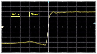
On the supplier's site, there is a nice screen dump of the screen of a 4 GHz oscilloscope showing the output signal of the PCB. We publish this in the image below, but keeping in mind the saying 'that’s like marking your own homework'. We do not have an oscilloscope with such bandwidth, so we cannot verify this claim. But the data-sheet from Analog Devices is clear regarding the rise time of the ADCMP606.
 |
| The output signal of the PCB according to the supplier. (© Changsha Findra Trading) |
Our practical experience with this module
Connecting to the oscilloscope
You can connect the board to a 5 Vdc power supply using the USB cable provided. Afterwards, you plug the BNC connector into one of the inputs of your oscilloscope.
 |
| The PCB connected to our XDS2192A from OWON. (© 2023 Jos Verstraten) |
The output signal of the PCB
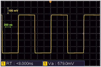
The oscillogram below shows the output signal of this 'fast edge pulse generator'. According to our oscilloscope, the amplitude of the output signal is 579.0 mV and according to our TFC-1000L frequency meter, the frequency is 1.000,005 MHz.
 |
| The output signal of the PCB. (© 2023 Jos Verstraten) |
Measuring the rise time and bandwidth of OWON's XDS2192A
According to the specifications, this oscilloscope has a bandwidth of 100 MHz and a rise time of 3.5 ns. According to the formula already mentioned:
Bandwidth (MHz) = 350 / rise time (ns)
these figures are therefore correct. Time to test this!
In the picture below, we set the time base to 5 ns/div. To put the rise time into perspective, we connected the output signal of our Philips pulse generator PM5704 to the second channel, set it to 1 MHz and terminated it with a 50 Ω terminator. According to Philips, this device has a rise time of 12 ns.
 |
| Measuring the rise time of the XDS2192A. (© 2023 Jos Verstraten) |
The XDS2192A measures its own rise time as 2.6 ns and that of the PM5704 as 13.7 ns. This time obviously includes the rise time of the oscilloscope itself. Two rise times cannot be simply added together. The formula for this is:
rise time generator = √ [(rise time measured)² - (rise time oscilloscope)²]
Calculated for this example:
rise time generator = √ [(13.7)² - (2.6)²]
rise time generator = √ [187.69 - 6.76)
rise time generator = √ 180.93
rise time generator = 13.45 ns
So in this way, you can calculate the rise time of signals with your rise time calibrated oscilloscope.

Fast edge pulse generator 180 picosecond rising edge
