|
If you search long enough, you can buy this digital low-frequency function generator module for less than € 12.00. Built in a box you pay € 20.00. Nice prices for a generator that generates all basic signals up to 65.5 kHz. This module is worth an extensive test. |
Introduction to the FG-050
Various names and various versions
This module is marketed under various names, such as 'FG-050', 'DDS Function Signal Generator Module' or '1Hz-65534Hz Digital DDS Function Signal Generator'. Some boards have the original color of the epoxy material, others are finished with a black lacquer layer. The print layout is identical and so are the components used. The fully assembled and adjusted module is offered for prices around € 15.00.
 |
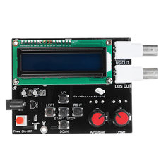
| The two sides of the module FG-050. (© 2018 Jos Verstraten) |
Via eBay we found one supplier who supplies this module in a housing. The PCB is slightly different, the push buttons are replaced by a connector for a flat cable that connects the PCB with the push buttons on the front panel. If you choose this version, you pay about € 20.00.
 |
| The module built into a plastic housing. (© eBay) |
If you own a 3D printer, you can print your own housing via the Thingiverse site. All necessary files are available for download here.
The properties of the FG-050
This digital function generator is a typical low frequency device. The frequency range of the DDS OUT output is only 1 Hz to 65,534 Hz. With two buttons you set the frequency, with two other buttons the shape of the output signal. You can choose between:
- Sine wave.
- Square wave.
- Triangle.
- Sawtooth.
- Reverse sawtooth.
- ECG.
- Noise.
- High Speed.
There are only two potentiometers available. One potentiometer is used to set the amplitude of the output signal on the DDS OUT output, the second to set a DC offset on this output.
With the fifth push button ON/OFF you choose either the OFF mode (you choose the shape and frequency of the signal) or the ON mode (the signal appears on the output).
There is also a second output, HS OUT, where only rectangular High Speed signals appear with four fixed frequencies up to 8 MHz.
The specifications of the FG-050
- Supply voltage: 7.0 Vdc to 9.0 Vdc
- Frequency DDS OUT: 1 Hz to 65,534 kHz
- Frequency HS OUT: 1 - 2 - 4 - 8 MHz
- Resolution setting frequency DDS OUT: 1 - 10 - 100 - 1,000 - 10,000 Hz
- Amplitude DDS OUT: 15 Vpeak-to-peak max.
- DC offset DDS OUT: 5 Vpeak-to-peak max.
- Output impedance DDS OUT: 200 Ω max.
- Display: LCD, 16 x 2 characters (type 1602)
- Dimensions module: 10.0 cm x 8.0 cm x 3.5 cm
The electronics in the FG-050
In the figure below a part of the wiring diagram of the FG-050 is shown, the part that is responsible for generating the output signals. We apologize for the poor quality of this scheme, but it is the only we could find and we found it such interesting information that we did not want to withhold it from you. It gives a good impression of how the FG-050 works.
The heart of the circuit is of course the microcontroller, an ATMEGA16A. To the left of this chip you will undoubtedly recognize the crystal that generates the clock, together with its two capacitors. Below is the reset and the indication LED circuit. The five push buttons directly control the PD inputs/outputs of the microcontroller. Note that the HS OUT output is also directly connected to one of these pins! On the bottom left, the eight PA outputs go to the resistive digital to analog converter. This cheap device uses an R/2R converter. Simple, but not too good in terms of high-frequency properties! The parasitic capacities of the resistors influence the pulse reproduction of such a R/2R-DAC to a large extent. The analog signal is processed in a double op-amp of type NE5532. In the first op-amp the DC offset is added to the signal, in the second op-amp the amplitude of the output signal is set. The DDS OUT output is directly connected to the output of the second op-amp.
In the middle of the diagram is the ON/OFF switch. The power supply is not shown in this figure. The 9.0 Vdc power supply is stabilized with a 78L05 for the microcontroller. With an ICL7660S, supply voltages of ±12 V are derived from the +9 V to supply the two op-amps symmetrically.
 |
| The diagram around the microprocessor. (© 2018 Jos Verstraten) |
After removing the PCB you can easily recognize the various blocks of the electronics, see picture below.
 |
| The components on the PCB. (© 2018 Jos Verstraten) |
Working with the FG-050
First set the resolution!
After switching on the unit, the output goes to the last set parameters. The first thing you have to do is to set the frequency to the new value. You only have two buttons, LEFT and RIGHT, to do this. With LEFT you reduce the frequency, with RIGHT you increase this quantity. It is useful to set the 'Frequency Step' first. This value determines by how much Hz the frequency increases or decreases when you press one of these buttons. You can choose between 1 Hz, 10 Hz, 100 Hz, 1 kHz and 10 kHz. If the frequency is set to 1 kHz and you want to set it to 50 kHz, it is not convenient to set the Step to 1 Hz, you have to press the 'RIGHT' button for far too long. You then set the Step to 10 kHz. You do this as follows. First press the START/STOP button until 'OFF' appears in the display. Press the UP button until 'Freq Step' appears in the display. You can use the LEFT and RIGHT buttons to set the desired step value.
 |
| Selecting the resolution of the frequency setting. (© 2018 Jos Verstraten) |
Select the desired waveform with the UP and DOWN buttons and the desired frequency with the LEFT and RIGHT buttons. In most cases it will be necessary to reset the Step to a lower value during this last operation, so that you can adjust the frequency to one Hz accurately if necessary.
 |
| Setting a sine wave signal with a frequency of 1 kHz. (© 2018 Jos Verstraten) |
Finally, press the START/STOP button until 'ON' appears on the display. Depending on the selected waveform, the signal appears on one or the other BNC output.
The FG-050 is being tested
Generating sine waves
It will be clear that the FG-050 reproduces a 1 kHz sine wave without problems and visible distortion. However, if you set the amplitude potentiometer to the maximum value, the signal get stuck against a positive threshold of +8.0 V and a negative threshold of -6.9 V. Setting a DC offset at this value of the output voltage makes no sense at all. The maximum peak-to-peak value that supplied our test sample was 14.9 V, which is in accordance with the specification given by the manufacturer (15 V).

More interesting is to investigate what the signal looks like at the maximum frequency of 65,534 kHz. In the oscillogram below you see this. The two horizontal cursor lines indicate the signal tops at a frequency of 1 kHz. This oscillograph shows three things. At this frequency there is a considerable harmonic distortion on the output signal. Moreover, the peak-to-peak value of the output signal has decreased a bit compared to that at 1 kHz. The frequency differs slightly from the set value, 65.536 kHz instead of 65.534 kHz.
 |
| The maximum sine wave signal at the maximum frequency of 65.534 kHz. (© 2018 Jos Verstraten) |
That the R/2R-ADC has very bad high frequency characteristics is shown by the generation of rectangle pulses. Even a pulse with a frequency of 20 kHz is displayed with unreasonably large rise and fall times, see left oscillogram below. At 65 kHz the quality of the signal becomes even worse, see the right oscillogram.
 |
| Rectangle pulses of 20 kHz and 65 kHz. (© 2018 Jos Verstraten) |
The generation of a sawtooth is ideal to test the linearity of the DAC. With every increase or decrease of the digital code with one bit, the analog voltage must decrease or increase with a small but always equally step. The sawtooth must be completely straight in an ideal case. With an R/2R-DAC this is only to be expected if for all resistors in the network extremely accurate components are applied, preferably with a tolerance of 0.1 %. With a cheap device like this FG-050, this is of course not the case. This is shown by the oscillogram below, where two kinks are present in the saw tooth. These kinks indicate a non-linearity in the digital to analog converter. This can already be caused by one resistor from the chain of sixteen, which happens to have a slightly higher or lower value than the others.
 |
| Test of the linearity of the DAC by generating a sawtooth. (© 2018 Jos Verstraten) |
For some unclear reasons, all cheap function generators produced in China have the ability to generate an ECG pulse. An ECG is a graphical representation of the electrical activity in the heart muscle. The letters ECG stand for 'ElektroCardioGraph'. In the image below you see on the left the pulse that generates the FG-050 and on the right what an ECG pulse of a healthy person should look like according to the medical booklets.
 |
| The ECG pulse of the FG-050 compared to the ideal pulse. (© 2018 Jos Verstraten) |
As shown in the wiring diagram, these pulses come directly from the microcontroller. The FG-050 generates these pulses when you select the option High Speed with the UP and DOWN buttons and then set the frequency to 1 MHz, 2 MHz, 4 MHz or 8 MHz with the LEFT and RIGHT buttons. Don't forget to move your cable to the upper BNC connector! As shown by the oscillograph below, these pulses have an amplitude of 5 V. The blue horizontal line represents the 0 V reference. It should be noted that the quality of the pulses depends to a large extent on the shielded cable used. This picture was taken with a compensated 1/10 probe connected to the BNC connector. With a 1/1 cable there is even more overshoot and ringing on the pulse, probably caused by the impedance of the cable.
 |
| The High Speed output set to a frequency of 8 MHz. (© 2018 Jos Verstraten) |
The big disadvantage of these extremely cheap devices is that no attention is paid to the amplitude setting. A simple potentiometer is not useful for practical applications in the lab. Suppose you want to use the FG-050 to test the sensitivity of an audio power amplifier. You connect the function generator, set to a 1 kHz sine wave, to the input of the amplifier, connect an AC voltage meter to the loaded output and increase the input voltage until the amplifier delivers the specified power. You can then measure the input voltage and you know the sensitivity of the amplifier. However, if you turn the potentiometer of the FG-050 back so far that the generator delivers a voltage of 100 mV, the signal below will appear on the DDS OUT. The 1 kHz sine wave is completely distorted by remnants of the microcontroller's clock signal. If you apply such a signal to the input of an audio amplifier, there is a chance that the power transistors will break due to too much high-frequency thermal energy.
There is only one remedy for this imperfection. Connect the output of the function generator to a fairly low impedance and well shielded 1/10 resistance divider. You don't have to shut down the amplitude potentiometer on the FG-050 almost completely to generate 100 mV.
 |
| A 1 kHz sine wave of 100 mVrms is heavily polluted by HF noise. (© 2018 Jos Verstraten) |
General conclusion
The FG-050 is a usable function generator for the undemanding electronics hobbyist. In the audio range from 10 Hz to 20 kHz, the generator provides excellent usable signals, assuming you connect a 1/10 or even 1/100 resistance divider to the output. It's a pity you don't get an output signal when you set the frequency. Quick testing of an audio amplifier by sweeping the frequency with one potentiometer-turn from 20 Hz to 20 kHz is therefore not possible. A pity, because with the push button control it could have been done easily.

GeekTech FG-050 DSS Function Generator