|
The FG-100 is a small digital function generator for low frequency applications offered for prices around € 30.00. The FG-100 generates sine waves up to 500 kHz and rectangle, triangle and sawtooth waves up to 20 kHz. |
Introduction to the FG-100
The specifications
We start with what is most important for every electronics hobbyist, the specifications of the FG-100:
- Waveforms: sine, rectangle, triangle, positive and negative sawtooth
- Sine wave frequency range: 1 Hz ~ 500 kHz
- Rectangle wave frequency range: 1 Hz ~ 20 kHz
- Triangle wave frequency range: 1 Hz ~ 20 kHz
- Sawtooth wave frequency range: 1 Hz ~ 20 kHz
- Output voltage: 0 V ~ ±10 Vpeak-to-peak
- Output impedance: 50 Ω
- Sine wave distortion: less than 1 % (1 kHz)
- Frequency setting resolution: 1 Hz
- DC offset: ±10 V max.
- Display: LCD1602, 2 x 16 characters, 58 mm x 9.4 mm
- Microcontroller: ATMega48, 8 bit
- Supply voltage: 3.5 Vdc ~ 10 Vdc
- Supply current: 300 mA typical
- Dimensions: 140 mm x 80 mm x 35 mm
- Weight: 184 g
The FG-100 DDS function generator
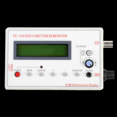
The FG-100 is supplied in a sturdy plastic housing. The front is not printed on this, but on a solid self-adhesive foil that is glued to the housing. We ordered two specimens for this test, with one this foil was loosened in a corner, which unfortunately caused an ugly fold in the front. On some models the manufacturer 'EZM Electronics Studio' is mentioned, other suppliers however deliver a housing without mentioning the manufacturer.
 |
| Despite the low price, the FG-100 looks very presentable. (© Banggood) |
To save money, the FG-100 is delivered without power supply. You must power the unit from a stabilized DC voltage between 3.5 V and 10 V. On the left side is a standard 3.5 mm power connector. The device is delivered with a relatively short power cable that ends in a USB-A connector. For the tests we have used a stabilized mains power supply set to 5.0 V.
Operating the FG-100
The low price obviously means that the designers have removed all expensive components such as rotary switches and accurate potentiometers. You need to operate the device with eight push buttons and two low-cost potentiometers.
 |
| The function of the ten control buttons. (© 2018 Jos Verstraten) |
Working with the FG-100
A strange choice!
Operating the FG-100 is not as convenient as you would expect from a handy function generator. When the device is switched on, the software sets the FG-100 to a 100 kHz sine wave with the device in STOP mode. Be careful! A DC voltage of -10 V appears on the output when the amplitude potentiometer is fully open. After pressing the RUN/STOP button, the generator delivers the promised sine wave with a frequency of 100 kHz and a peak-to-peak value of ±10 V. A strange choice of the designers, more convenient would be a start-up frequency of 1 kHz, because 100 kHz is completely outside the specified range for rectangle, triangle and sawtooth. These are only specified up to 20 kHz.
 |
| The FG-100 starts with a 100 kHz sine wave. (© 2018 Jos Verstraten) |
To set the output frequency to another value, follow these steps:
- Press the RUN/STOP button, the output voltage goes to 0 V.
- Use the CURSOR button to select the digit you want to adjust, this digit will flash.
- Use the + and - buttons to set the digit to the desired value.
- Finally, press RUN/STOP again, the output delivers a sine wave at the selected frequency.
Setting the waveform
- Press the RUN/STOP button, the output voltage goes to 0 V.
- Press the MODE button until the desired waveform appears on the display.
- Finally, press RUN/STOP again, the output provides the selected waveform.
Adjusting the amplitude
One potentiometer is available on the right side of the housing. At this point you will have to deal with the limitations of such a cheap device. In addition to an amplitude potentiometer, professional function generators also have a rotary switch with which you can select the decade of the output voltage:
- 0 mV to ±10 mV.
- 0 mV to ±100 mV.
- 0 V to ±1 V.
- 0 V to ±10 V.
With such a setting, it is no problem to set the output voltage to 5 mV to control a sensitive microphone amplifier. However, with the FG-100 with its one potentiometer setting between 0 V and ±10 V, this does not work. Even if you open the potentiometer slightly, the FG-100 already delivers a voltage of ±100 mV, with a lot of noise and quantisation effects. To get useful mV signals from the FG-100, you need to connect an external voltage divider to the output.
 |
| The disadvantage of only one amplitude potentiometer: it is impossible to set a small clean voltage. (© 2018 Jos Verstraten) |
This option allows you to superimpose an adjustable DC voltage on the output signal. This option is enabled by pressing the DC OFFSET ON/OFF button and turning the potentiometer on the front panel. Please note that the output voltage is limited to +10 V and -10 V and that the usability of this option is very limited.

Switching on a LPF-filter
The FILTER push button is supposed to switch on a low-pass filter to minimize the quantification noise on the output signal. However, we have not been able to determine the function of this filter for either of the two test specimens. Even if a rectangle of 20 kHz is generated, no difference can be seen on the scope with or without filter.
The electronics in the FG-100
What does DDS mean in the name of the device?The device is officially called the 'DDS Function Generator'. The acronym DDS stands for 'Digital Data Storage'. It is a reference to the way in which the FG-100 generates its output signals. If you analyze one period of a sinusoidal signal, you can compile this period from a large number of consecutive voltage samples that make up the sine wave. These samples can be translated into digital codes. You can reconstruct the period of the sine wave by presenting all these codes one by one to a digital to analogue converter, a DAC. The DAC then provides a 'stepped approach' to the period of the sine wave.
That's exactly what happens in the FG-100 and all other digital function generators. In the memory of the microcontroller ATMega48 digital data are stored, which form the digital representation of the waveforms sine, rectangle, triangle, positive sawtooth and negative sawtooth. If you set the FG-100 to a certain waveform and a certain frequency, the software will put the data from the memory in the right order and at the right speed on the eight data lines. Via a DAC, these digital samples are converted into analogue samples that compose the step approach to the desired output signal.
 |
| The principle of the stepped approach of the output voltage. (© 2018 Jos Verstraten) |
The double-sided PCB looks very professional. Because the power supply is at least +3.5 Vdc and the output can be ±10 V, a lot of electronics must be present in the power supply. The core of this part of the circuit is an MC34063A switched voltage multiplier, followed by two diode rectifiers for the positive and negative supply voltages and an AMS117 stabilizer for 5 V. Three electrolytic condensers smooth out the three supply voltages +13.0 V, -13.0 V and +5.0 V.
The analog output stage is built around two operational amplifiers TL072C. With their bandwidth of 3 MHz and slew-rate of 13 V/µs, they determine the maximum frequency range for the waveforms rectangle, sawtooth and triangle. These waveforms contain many high harmonics that are attenuated by the limited bandwidth of these operational amplifiers.
 |
| The PCB of the FG-100 contains three clearly distinguishable functional parts. (© 2018 Jos Verstraten) |
Under the microcontroller you will find a lot of resistors. These components represent the digital to analog converter, which converts the data from the memory of the microcontroller into an analog voltage. Such a DAC is called an 'R-2R DAC' and that is the simplest and cheapest DAC circuit that exists. The principle is shown in the figure below. With the network theory it can be proven that a stepped voltage is created at the output of the op-amp when you increase the digital codes at the input from 'L-L-L-L-L-L-L-L-L-L-L' to 'H-H-H-H-H-H-H-H-H' and then decrease to 'L-L-L-L-L-L-L-L-L' again. You get a stepped approximation of a triangle on the output. By adjusting the codes you can approach a sine, rectangle or sawtooth in the same way.
The disadvantage of this inverter is obvious. All points of this circuit have parasitic capacities to ground. Together with the resistors, these form low-pass filters that adversely affect the reproduction of high frequencies.
 |
| The basic circuitry of an R-2R digital to analog inverter. (© 2018 Jos Verstraten) |
The FG-100 on the test bench
The function generator in practice
All tests were performed with a load of 1 kΩ. Terminate the device with this resistor hardly affects the amplitude of the output signal. From the slight voltage drop, we could calculate that the output impedance is equal to 45.4 Ω, almost equal to the specified 50 Ω. All oscillograms are made with a Hantek DSO5102P digital oscilloscope.
The sine waveform
We have tested the sine waveform for frequencies of 1 kHz, 10 kHz, 100 kHz and 500 kHz. The amplitude of the output signal remains constant until 100 kHz and then decreases gradually. The signal shape remains good at first sight, unfortunately we do not have a distortion meter available to measure the harmonic distortion. The accuracy of the frequencies is excellent, as can be expected from a digital system.
 |
| The sine wave output for frequencies of 1 kHz, 10 kHz, 100 kHz and 500 kHz. (© 2018 Jos Verstraten) |
We have tested the rectangular waveform for frequencies of 1 kHz, 10 kHz, 20 kHz and 100 kHz. The amplitude of the output signal remains constant. As expected, the rise and fall times take up an increasing part of the total signal period. The rise time of the pulse is 1.36 µs, independent of the frequency setting. This corresponds to a slew rate of 7.2 V/µs, much less than the used op-amps can handle. Probably the parasitic capacities in the R-2R network cause the deterioration of the slew-rate of the device.
 |
| The rectangular wave output for frequencies of 1 kHz, 10 kHz, 20 kHz and 100 kHz. (© 2018 Jos Verstraten) |
 |
| Measurement of the rise time of the leading edge of the rectangular output voltage. (© 2018 Jos Verstraten) |
These signals are not very interesting because you will rarely use them in practice. At 1 kHz the waveform is of course excellent, you can see what it looks like at 20 kHz and 100 kHz in the oscillograms below.
 and 100 kHz (below).") |
| Sawtooth and triangle of 20 kHz (above) and 100 kHz (below). (© 2018 Jos Verstraten) |
The software allows to set the display to 999,999 Hz. Of course, we were curious about the output voltage at this frequency, which is completely outside the specified range. To our surprise, the device delivers a usable sine wave, although considerably attenuated compared to the reference sine wave at 1 kHz. As the left oscillogram shows, there is a slight modulation on the signal. Moreover, the output signal is not symmetrical relative to the ground. The other waveforms result in completely chaotic output voltages like the 'rectangle' in the right oscillogram.
 |
| Sine and rectangle waveform at 999,999 Hz. (© 2018 Jos Verstraten) |
Our opinion about the FG-100
Our tests show that the FG-100 is an excellent signal generator for the hobby workshop. However, on one condition. You have to complete the device yourself with a three-position output attenuator, which attenuates the output signal of the FG-100 with the factors 1/1, 1/10 and 1/100. Without such an addition, an accurate setting of the output voltage is absolutely impossible.

FG-100 DDS Function generator