
|
Semiconductor tester, Vdc meter, RLC meter, continuity tester, oscilloscope, function generator, IR decoder, voltage source. With the DSO-TC3 from FNIRSI, you can do anything! But how accurate do all these functions work? We tested it! |
Introduction to the DSO-TC3 from FNIRSI
What is the DSO-TC3?
The manufacturer calls the DSO-TC3 a 'digital multimeter'. However, you should not think of the standard interpretation of the word 'multimeter', because then you do this unique meter a great injustice. Indeed, the DSO-TC3 can do much more than the standard multimeter:
- Measure DC voltage up to 40 V with 1 mV resolution
- Identify semiconductors
- Measure zener voltages up to 24 V
- Measure resistors, capacitors and inductors
- Measure continuity
- Read out the DS18B20 temperature sensor
- Read out temperature and RH sensor DHT11
In addition, the device is also a:
- Oscilloscope up to 500 kHz
- Function generator up to 100 kHz and 3.3 Vpeak-to-peak
- DC voltage source up to 3.3 V
- IR code decoder
The appearance of the DSO-TC3
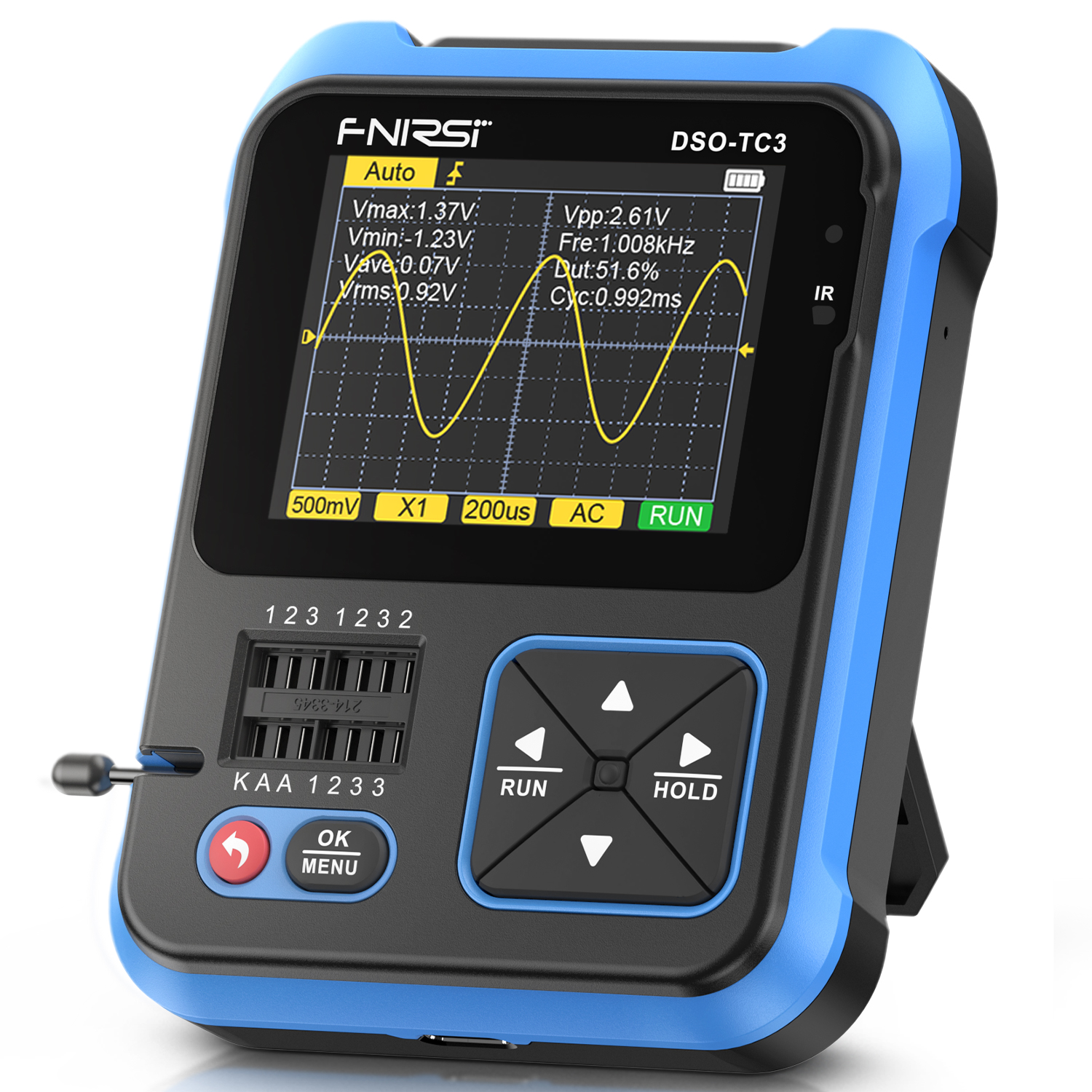
The DSO-TC3 is housed in a trendy-looking plastic case measuring 110 mm x 76 mm x 30 mm and weighing 128 grams. The back features a fold-out bracket, allowing you to place the device in a convenient reading position on your table.
The meter is powered from an internal lithium-polymer battery with a 1,500 mAh capacity that you can power via USB-C connector from a standard 5 V mains supply. The maximum charging current is 0.78 A. With a fully charged battery, we measured it, you can work with the meter for about six and a half hours.
The device communicates with its user via a 2.4-inch TFT colour display.
 |
| The DSO-TC3's appearance. (© Banggood) |
Manufacturer, suppliers and price
The DSO-TC3 is marketed under the brand name FNIRSI by Chinese Shenzhen FNIRSI Technology Co. from (obviously) Shenzhen. You can order the little device from all well-known mail-order companies such as Banggood, Amazon, eBay and countless companies that sell their stuff via AliExpress. Prices vary slightly, you should pay around 50 euros for this multi-universal meter.
The DSO-TC3 viewed from all sides
In the composition picture below, we have collected the three main views of this device. The bottom side contains only the USB-C connector for connecting the charging cable. The top side is more interesting and contains three MCX connectors:
- IN(0-40V): Input for the Vdc measurement function
- DDS: Output for the function generator
- DSO: Input for the oscilloscope
On the right side is a small hole behind which there is a push button switch. This allows you to reset the device in case of an unexpected hang-up. However, this never occurred in all our experiments.
In addition to the screen, the front panel contains six push buttons to operate the device. Despite the multitude of functions, the operation is fairly quickly clear and self-explanatory. Next to these buttons, the last component is something that we find an abomination: a 14-pin 'zero insertion force' IC socket (ZIF socket) with its associated little handle. Why not mount three 2 mm sockets on the front panel? The necessity of such an IC socket completely escapes us. You really won't pry most of the components to be tested into the tiny holes of that socket, but connect them via the three supplied cables. Too bad FNIRSI has slavishly followed the countless Chinese manufacturers who market semiconductor testers with such a clumsy IC socket!
 |
| Three views of the DSO-TC3. (© 2023 Jos Verstraten) |
The scope of delivery
For your fifty euros, you get not only the little meter, but a lot of cables to connect the DSO-TC3 to the outside world. In the picture below, we have clearly summarised everything you receive:
- Three 20 cm cables with hook-clips that fit into the IC socket
- A 45 cm USB-C to USB-A charging cable
- A standard measuring probe with BNC connector and 1/10 switch
- A BNC to MCX adapter plug
- A 60 cm MCX to crocodile cable
- A bilingual manual
All this is in a nice cardboard box, internally fitted with a thick foam insert, in which the meter is well protected. Under this insert is room for the cables and the manual.
 |
| The scope of delivery of the DSO-TC3. (© 2023 Jos Verstraten) |
The manual
The manual provided is a very well-crafted 68-page A-5 booklet explaining in Chinese and excellent English all the functions of the little device. We have scanned the English part and saved it on our account on archive.org for you:
The English part of this manual does contain some errors. For example, it claims that the frequency range of the function generator is either 10 kHz or 100 kHz, depending on the signal shape. In the one supplied to us, all waveforms can be set up to 100 kHz. Furthermore, transistors are consistently called 'triodes', even though they are quite different components. That a zener diode is a 'regulated diode' is also new to us.
The specifications of the oscilloscope
According to FNIRSI, the built-in oscilloscope has the following specifications:
- Sampling rate: 10 Ms/s
- Analogue bandwidth: 500 kHz
- Input resistance: 1 MΩ
- Vertical sensitivity: 10 mV/div ~ 10 V/div (1/2/5 sequence)
- Vertical coupling: AC/DC
- Time base: 1 μs/div ~ 10 s/div (1/2/5 sequence)
- Trigger mode: Auto/Normal/Single
- Trigger type: rising or falling edge
- Numeric data on screen: eight
- Automatic setting: yes
- RUN/STOP: yes
Function generator specifications
- Signal shapes: sine, rectangle, pulse, triangle, sawtooth, DC voltage
- Frequency range: 1 Hz ~ 100 kHz
- Resolution frequency setting: 1 Hz
- Peak-to-peak voltage: 0.1 V ~ 3.3 V
- Resolution voltage setting: 0.1 V
- Output resistance: unspecified
DC voltage meter specifications
- Range: 0 Vdc ~ 40.000 Vdc
- Resolution: 1 mV
- Input resistance: unspecified
Semiconductor tester specifications
- Recognisable components: diode, zener diode, bipolar transistor,
- Recognisable components: MOSFET, thyristor, triac
- Measurable parameters: hfe, Vbe, Ic, Iceo, Ices, Vf, Cg, Id, Vgs, Rds
- Identification of connections: yes
The parameters displayed obviously depend on the component under test.
The specifications of the RLC meter
- Resistance measurement range: 0.01 Ω ~ 50 MΩ
- Resolution resistance measurement: 1999
- Capacitance measuring range: 5 pF ~ 100 mF
- Resolution capacitance measurement: 1999
- Induction measurement range: 10 μH ~ 1,000 mH
- Resolution self induction measurement: 1999
The electronics in the FNIRSI DSO-TC3
Opening the case
At first, the housing seems impossible to open. A more thorough inspection reveals that the black front panel is snapped into the blue case and is easily removed with a knife. Under this front panel are four small screws that fasten the two parts of the case together.
A tip: if you ever want to open a DSO-TC3, after removing the black front panel, fix the display to the blue part of the case with a few pieces of adhesive tape.
The electronics
After opening the case, it turns out that the entire electronics are present on one PCB. Above, you can see the three MCX connectors that are soldered directly onto the PCB, without additional mechanical support. Because quite some forces are exerted on those connectors when plugging and unplugging the cables, this is not very reliable in the long run.
A TC4056A is used as the battery charger. From the low battery voltage, the higher supply voltages for the analogue electronics are generated by means of the necessary charge pumps. A 7660 voltage converter helps generate the negative supply voltage.
On the PCB, we also recognise a CD4051 analogue multiplexer and a COS724. This is a universal amplifier from the Chinese brand Cosinus. We cannot find any data about the chip MZE6247. In the centre of the PCB is the FPGA (Field Programmable Gate Array), no doubt specially programmed for this device, without any identification on it.
What intrigues us is the lower half of the PCB. There we count no fewer than 33 apparently identical transistors, together with dozens of resistors. If we didn't know better, we might think of an old-fashioned triangle-to-sine converter, as used in the XR2206, for instance. But in such a modern device as the DSO-TC3, the sine wave will no doubt be generated via a DAC with low-pass filter. Perhaps one of our readers can figure out what all those transistors are for.
 |
| The electronics in the case. (© 2023 Jos Verstraten) |
Working with the FNIRSI DSO-TC3
Switching on
The DSO-TC3 switches on after a short press on the red 'Enter' button. Immediately, a selection screen appears where you can select one of the four main functions of the device using the '◄' and '►' keys:
- Generator
- Tools
- M-tester
- Oscilloscope
The selection is confirmed after pressing the 'OK/MENU' key.
 |
| The four functions of the main menu. (© 2023 Jos Verstraten) |
Working with the Generator
After selecting this function, you will see the screen below appear on the display. You start by selecting the desired signal shape using the '▼' and '▲' keys:
- Sine
- Square
- Pulse
- Triangle
- Ramp
- DC
Press '►/HOLD', then '▼' and '▲' to select the parameter to be adjusted (frequency, voltage, duty-cycle). Then press '►/HOLD' again, you can then use '▼' and '▲' to adjust the value of the parameter. Finally, press '◄/RUN' twice to exit programming.
Remember that the voltage does not represent the rms value, but the peak-to-peak value of the signal!
 |
| Programming the function generator. (© FNIRSI) |
Working with the Oscilloscope
After selecting this function, the screen below immediately appears on the display. The eight numeric data are automatically projected over the oscilloscope image, an extremely irritating use. After all, most of that data is not very relevant and just gets in the way. Fortunately, you can remove that data from the screen by long pressing the '►/HOLD' button.
After pressing the 'OK/MENU' button, the automatic function is switched on and the software searches for the best settings for the signal.
Of course, you can also set up the oscilloscope manually. Below the screen are four yellow data boxes representing the oscilloscope's main settings. You can select one of those boxes with the '◄/RUN' and '►/HOLD' keys. Besides the four settings listed, you can also select the trigger settings, baseline and trigger level in this way. The option you selected is displayed in blue. You can afterwards adjust its value with the '▼' and '▲' keys.
A long press on the '◄/RUN' key moves the oscilloscope from 'RUN' to 'STOP' and freezes the image.
 |
| The screen of the oscilloscope. (© FNIRSI) |
Working with the M-Tester
After selecting the 'M-Tester' function, the screen below appears on the display. You should then connect the component to be tested or measured to the IC socket. For zener diodes, you should use the 'A' and 'K' contacts, where 'A' obviously refers to anode and 'K' to cathode. All other components should be connected to contacts '1', '2' and (if applicable) '3'. Afterwards, press the 'OK/MENU' button. The DSO-TC3 will write 'testing' on its display and after a few seconds the results will appear on the screen.
 |
| The screen of the 'M-Tester' function. (© FNIRSI) |
Working with the Tools
Funny thing is that the programmers made a mistake in the opening screen of this feature. Instead of 'Continuity' as the first option, it says the Chinese word 'Tongduan'. This function allows you to make some rather different measurements:
- Tongduan:
The meter will beep if the resistance between two connections is less than 100 Ω. - Voltage:
Measures DC voltages up to 40,000 V. - DS18B20:
Displays the temperature recorded by this popular temperature sensor from Dallas. Range is 0 °C to +85 °C. - DHT11:
Ditto for this equally popular Chinese temperature and RH sensor. Range 0 °C to +60 °C and 5 %RH to 95 %RH. - IR Decode:
Decode the infrared codes transmitted by an IR remote control according to the NEC protocol. However, most remote controls used in Europe do not work with this protocol. The DSO-TC3 cannot deal with these European systems. - Calibrate:
Calibration of the meter which means compensating for the parasitic properties of the connecting cables.
 |
| The opening screen of the 'Tools' function (© FNIRSI). |
The 'Setup' menu
If you long press the '◄/RUN' key, the setup menu below appears on the screen. The options of this menu are clear even without explanation.
 |
The 'Setup' menu. (© FNIRSI) |
Testing the DC voltage meter
Accuracy in measuring DC voltages
In this and subsequent tests, the parameters measured or generated with the DSO-TC3 are compared with our laboratory equipment. A Fluke 8842A is used for the DC voltage function. We set the test voltages with a stabilised linear power supply, for voltages up to and including 1 V terminated with a 1/9 voltage divider. You can see the results of these measurements in the table below.
 |
| Accuracy in measuring DC voltages. (© 2023 Jos Verstraten) |
The input resistance
To measure DC voltages with a resolution of up to 1 mV, the input resistance of the meter must be quite high, at least 10 MΩ. This is because that resistance loads the point at which is measured, with the result that a lower voltage is always measured than is present without a voltmeter connected. We tested this parameter by including our multimeter ET3255 from East Tester in series with the positive measurement lead, switched as a μA meter. At an input voltage of 10 V, we measured a current of 62.29 μA. Using ohm's law, you can calculate that this corresponds to an input resistance of about 160 kΩ. This is far too low to make meaningful measurements down to 1 mV! Indeed, by connecting such a low resistor, the voltage at the measurement point will be many tens of mV lower than it is without a meter. This measurement error makes measuring with a resolution of 1 mV an absolutely pointless activity!
Testing the function generator
The sine wave output
The generator is set to a sine wave signal with a frequency of 100 kHz and a peak-to-peak value of 3.0 V. The output voltage is observed on our OWON oscilloscope XDS2102A. You can see the result in the left oscillogram below. If we magnify this signal considerably by increasing both the time base and the vertical gain, we get a nice example of the famous 'staircase approach' that every digitally constructed analogue signal consists of, see right oscillogram. The sharp edges of the steps of the staircase have been nicely 'worn down' by applying analogue low-pass filtering to the signal coming out of the DAC. No overshoots, glitches or other peculiar pulses can be detected. Moreover, the DAC conversion appears to be perfectly monotone: all the steps are, to the eye, the same size. Neat!
 |
| The sine wave of 100 kHz and 3.0 Vptp. (© 2023 Jos Verstraten) |
Generator output resistance
Professional function generators all have an output resistance of 50 Ω. Would this also be the case with the DSO-TC3? We measure this by first measuring the unloaded output voltage and then loading the output with a 50 Ω resistor. To measure accurately, we reduce the frequency to 1 kHz and measure the output voltage with our ET3255 multimeter from East Tester:
- Unloaded: 1.049 Vrms
- Loaded with 50 Ω: 0.150 Vrms
Across the generator's output resistance, a voltage of 1.049 V minus 0.150 V is 0.899 V falls. If 150 mV arises across a resistance of 50 Ω, it is clear that 899 mV arises across a resistance that is six times higher, i.e. 300 Ω. So that is the value of the internal resistance of the generator.
The accuracy of the output voltage
We measure this at a sine voltage with a frequency of 1 kHz. We set the output voltage of the generator to a number of values and measure the actual output voltage with our ET3255 multimeter. However, this does not measure peak-to-peak values, but rms values. The rms value of a voltage is equal to the peak-to-peak value divided by 2.82. So the voltage set on the DSO-TC3 must always be divided by this factor to compare with the voltage measured on the ET3255. The results are summarised in the table below.
 |
| The accuracy of the sinusoidal output voltage. (© 2023 Jos Verstraten) |
Harmonic distortion THD on sine wave voltage
We determine this parameter at a peak-to-peak voltage of 3.0 V and at three different frequencies using our HP331A distortion analyser:
- 1 kHz ➡ THD = 0.57 %
- 10 kHz ➡ THD = 0.45 %
- 100 kHz ➡ THD = 0.21 %
In the oscillogram below, you can see the generator output signal at 100 kHz above and the filtered-out harmonics below. Clearly you can see the HF distortion due to the residuals of the stepped approximation of the output voltage.
 |
| The harmonic distortion at 100 kHz. (© 2023 Jos Verstraten) |
The appearance of the smallest sinusoidal voltage
Digital function generators are known to rather contaminate small output signals with digital noise, spikes and residues from the DAC process. The lowest voltage the DSO-TC3 can generate is 100 mVpeak-to-peak. We looked at that at 1 kHz. Hardly any digital noise, but unfortunately heavy distortion of the negative peak of the sine wave!
 |
| The smallest sine wave voltage at 1 kHz. (© 2023 Jos Verstraten) |
Note
The pulse output voltage
The DSO-TC3 does not provide a nice symmetrical sine wave voltage. The sine wave is superimposed on a positive DC voltage of up to about +1.5 V, depending on the signal magnitude setting.
The rectangular signal
We measure at 100 kHz, the amplitude is now not adjustable but fixed at 3.3 V. The rectangular voltage produced by the DSO-TC3 is shown in the oscillogram below. Not bad for such a cheap little device! The oscilloscope reports an amplitude of 3.220 V.
 |
| The square-shaped output voltage at 100 kHz. (© 2023 Jos Verstraten) |
The pulse output voltage
The difference between square and pulse is that with the latter, you can set not only the frequency, but also the duty-cycle (the on/off ratio). You can set this parameter from 1 % to 99 %. This works well, just look at the oscillograms below where we show the output signal at a frequency of 1 kHz and a duty-cycle of 1 %. The blue trace is of course a time magnified representation of the yellow signal.
 |
| The pulse at 1 kHz and 1 % duty-cycle. (© 2023 Jos Verstraten) |
The accuracy of the DC voltage generated
An accurate DC voltage source is never out of place in the lab. Does the DC output of the DSO-TC3 fit this description? We set a number of DC voltages and measure the UNLOADED output voltage with our 8842A from Fluke. The word 'UNLOADED' is in capitals for a reason, because an accurate voltage source should have the lowest possible output resistance. The DSO-TC3, with its output resistance of 300 Ω, does not really meet this requirement. If you connect the source to something with an internal resistance of 10 kΩ, the output voltage of the generator will be significantly reduced. You should always keep this in mind!
 |
| The DC voltage of the function generator. (© 2023 Jos Verstraten) |
The accuracy of the frequency

We verify this by putting two equally large sine wave signals on the oscilloscope, one with a frequency of 1 kHz and the other with a frequency of 500 kHz. Of course, the vertical sensitivity setting is not changed. You can see the result in the oscillograms below.
We can be brief about that, it is excellent. Accurate down to the hertz!
Testing the oscilloscope
The bandwidth
In our experience, Chinese oscilloscope manufacturers tend to rather exaggerate the bandwidth of their products. So we are rather sceptical about the specification of a bandwidth of 500 kHz.
We verify this by putting two equally large sine wave signals on the oscilloscope, one with a frequency of 1 kHz and the other with a frequency of 500 kHz. Of course, the vertical sensitivity setting is not changed. You can see the result in the oscillograms below.
The 500 kHz sine wave is displayed smaller than the 1 kHz sine wave. After some measurements on the size of the peak-to-peak values of the oscillograms, we can conclude that the 500 kHz signal has only 85% of the magnitude of the 1 kHz signal. This corresponds to an attenuation of about -1.5 dB! This is a more than excellent value and FNIRSI is therefore not exaggerating the specified bandwidth at all.
 |
| Checking the bandwidth of the oscilloscope. (© 2023 Jos Verstraten) |
Display of a rectangular voltage
The figure below shows how the DSO-TC3 reproduces a perfect rectangular voltage with a frequency of 100 kHz. We are also more than satisfied with this. We have seen such cheap, small scopes show something different on their screen!
 |
| Display of a 100 kHz square wave. (© 2023 Jos Verstraten) |
Numerical measurement accuracy
The DSO-TC3 puts eight numerical data on the screen:
- Vmax: The maximum value
- Vmin: The minimum value
- Vave: The average value
- Vrms: The root mean square value
- Vpp: The peak-to-peak value
- Fre: The frequency
- Dut: On/Off ratio
- Cyc: The period
We don't see the point of all that data on the screen, at most the rms value, peak-to-peak value and frequency are important. How accurate are these measurements? We generate a 1 kHz sine wave signal with our Rigol function generator DG1022 and set exact rms values. We observe what the DSO-TC3 thinks of it and check in addition with our ET3255.
 |
| Accuracy of rms value measurement. (© 2023 Jos Verstraten) |
The automatic setting of the oscilloscope
After applying a signal, you need to press the 'OK/MENU' button for a while. The software then starts looking for the best settings of sensitivity and time base to display a good image of the signal on the screen. We really like this automatic setting. In most cases, it produces a fairly stable image of two periods on the display with about half the display height filled. Only for more complicated signals, like the example below, does the automatic setting fail. Then you have to start adjusting the trigger level with the push buttons to get a stable image.
 |
| You have to set such a signal manually. (© 2023 Jos Verstraten) |
Important note
It is not possible to use the function generator and oscilloscope simultaneously. When selecting 'Oscilloscope', the DDS output provides a symmetrical rectangle with a frequency of 1 kHz and an amplitude of 3.3 V by default.
Testing the M-Tester
Identifying semiconductors
We presented a handful of bipolar transistors, diodes, triacs, thyristors and MOSFETs to the DSO-TC3 and in all cases, the device managed to find out both the type and connections. We can't do much with the numerical data that appear on the screen for the simple reason that we don't have devices that allow us to check that data accurately. We do have a similar device, the TT-100 from Voltcraft, but it measures transistors with a different collector current, which makes comparison of the measurements questionable. Still, a few comparative numbers:
- 1N5822 schottky diode
Vka with DSO-TC3: 0.22 V
Vka with TT-100: 0.24 V - FR207 fast recovery diode
Vka with DSO-TC3: 0.63 V
Vka with TT-100: 0.61 V - BC107 transistor
hFE with DSO-TC3: 285 (Ic = 7.4 mA)
hFE with TT-100: 275 (Ic = 2.5 mA) - BC243 transistor
hFE with DSO-TC3: 142 (Ic = 7.4 mA)
hFE with TT-100: 137 (Ic = 2.5 mA) - 2N3055 transistor
hFE with DSO-TC3: 67 (Ic = 7.4 mA)
hFE with TT-100: 87 (Ic = 2.5 mA)
 |
| Identifying semiconductors. (© 2023 Jos Verstraten) |
Accuracy in resistance measurement
For this test, we have a set of accurate resistors available with a tolerance of ±0.1%. We measure these first with the DSO-TC3 and then, for verification, with our 8842A. The results are conveniently summarised in the table below.
 |
| Accuracy when measuring resistors. (© 2023 Jos Verstraten) |
Accuracy in capacitor measurement
When measuring capacitors, we use capacitors with a tolerance of ±1.0 %. We measure these first with the DSO-TC3 and for verification with our ET4401 RLC measuring bridge from East Tester. For electrolytics, we measure ordinary Chinese ones. For capacitors larger than 1 μF, the DSO-TC3 also measures the ESR, the 'equivalent series resistance'.
The results are again conveniently summarised in the table below. Because of the large errors on the low values, we repeated the measurements for verification, but this time with the capacitors pushed directly into the contacts of the IC socket. Hardly any difference! It is these results that are listed in the table.
 |
| Accuracy in measuring capacitors. (© 2023 Jos Verstraten) |
Accuracy in inductance measurement
We measure a set of coils with values from 1 μH to 10 mH. Again, we use the ET4401 RLC measuring bridge as a reference. Both meters also measure the series resistance of the coils. These values are also included in the table below.
 |
| Accuracy when measuring coils. (© 2023 Jos Verstraten) |
Our verdict on the FNIRSI DSO-TC3
We have a very mixed feeling about this device. It looks very nice, is affordable and, because of these features, is undoubtedly a nice little gadget that a lot of hobbyists will fall for.
But...a technical evaluation does not take into account such external features, but must answer the question of whether the DSO-TC3 is a good usable measuring device. As for the function generator and oscilloscope functions, we are quite positive. Both functions work, within the limitations of such a simple and inexpensive device, excellently.
As for the measurement functions, we have to be less positive. Both small capacitors and inductances are measured with large errors. The measured ESR values of electrolytics and series resistances of coils are also a joke.
About measuring a DC voltage with a resolution of up to 1 mV with a meter with an internal resistance of 160 kΩ, we have already clearly stated our opinion in the story: nonsense!

(Banggood sponsor ad)
FNIRSI DSO-TC3 Multifunctional Electronic Component Tester
FNIRSI DSO-TC3 Multifunctional Electronic Component Tester