|
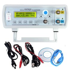
The FY3200S from Feeltech delivers signals up to 24 MHz on two fully independent adjustable outputs. Besides the standard signals, this generator also delivers sweeps, electrocardiogram pulses, white noise, AM and FM. The built-in frequency/pulse counter can be used up to 100 MHz. |
Introduction to the FY3200S from Feeltech
How does a function generator work according to the DDS principle?
DDS stands for 'Direct Digital Synthesis', generating analogue signals digitally. One period of an analogue signal is divided into a large number of steps and the size of each step is recorded in a digital code. All these codes form a digital 'signal shape table' that is stored in the memory. This signal shape table is read out with an adjustable frequency. The successive digital values are converted by a digital to analogue converter into an analogue voltage.
The great advantage of the DDS principle is that you can program any waveform in memory and then 'let it play' through the function generator. DDS generators of the better kind have an interface that allows you to connect the device to your PC. Using special software, you can compile a digital signal shape table on your PC for a specific signal shape and load it into the memory of the function generator.
What can the FY3200S do?
The device has, given the low price of around € 50.00, an impressive number of possibilities. In fact, you get two generators for the price of one, because you can program the two outputs CH1 and CH2 completely independently of each other. This is very simple. In the top left corner of the display you can see 'MF' or 'SF'. 'MF' means 'Main Function' and determines the programming of the yellow output connector CH1. 'SF' means 'Subsidiary Function' and determines the programming of the blue output connector CH2. To switch from one channel to another, press the buttons to the right of the BNC connectors. A second press of these buttons switches the channel off.
A third BNC connector, INPUT, is the frequency or pulse counter input. The only shortcoming of this counter is that there is no sensitivity control and the counter only responds if you apply at least 2 V peak-to-peak to this input.
What does the FY320S deliver?
An impressive number of fixed signals:
- Sine.
- Rectangle.
- Pulse.
- Triangle.
- Rising sawtooth.
- Falling sawtooth.
- DC voltage.
- Preset 1: Lorentz pulse.
- Preset 2: Multitone pulse.
- Preset 3: Random noise.
- Preset 4: Electrocardiogram pulse.
- Preset 5: Trapezoidal pulse.
- Preset 6: Sync pulse.
- Preset 7: Narrow pulse.
- Preset 8: Gaussian noise.
- Preset 9: Amplitude-modulated signal.
- Preset 10: Frequency-modulated signal.
- ARB 1 to ARB 4: four freely available memory locations.
In addition to these periodic signals, you can program two sweep signals, one with a linear sweep and the other with a logarithmic sweep. You can program the start, end and sweep time. The generator offers furthermore both Freqency-Shift-Keying (FSK) and Amplitude-Shift-Keying (ASK). In this case, either the frequency or the amplitude changes from one value to another by an external control signal.
Finally, you can of course set the value of all signals up to 20 V peak-to-peak, but you can also control the DC offset, duty cycle and phase difference between the signals on CH1 and CH2. On the back panel of the case you will notice two BNC connectors 'TTLA' and 'TTLB'. Two TTL-compatible signals appear synchronously with the signals on CH1 and CH2 to trigger a scope.
Save and Load functions
The FY3200S offers twenty memory locations, in which you can save the settings of a channel for later use.
Operation of the generator
A front panel with nine 'push buttons' and a rotary encoder are available for operating the unit. 'Push buttons' is written in quotation marks, because in fact they are nothing more than places on the plastic frontplate that are so weak that you can push them and thus operate miniature switches on the PCB. And that is the great weakness of this device. When you press in such a place, you do not press the underlying push button, but move the device backwards. You can only operate the FY3200S by pressing the top of the device firmly with your hand and pressing the buttons with your thumb.
What do you get for your money?
The FY3200S is delivered with two cables of the BNC to crocodile clamp type, a USB cable for connecting to your PC, a power cable and a small CD-ROM containing the manual in English plus some programs that make the communication between your PC and the generator run smoothly. Unfortunately, the power cable comes only with an American plug.
 |
| The FY3200S is delivered with an extensive cable set. (© 2018 Jos Verstraten) |
As is often the case with modern equipment, the enclosure is largely empty. The bottom plate shows a surprisingly small power supply board and a PCB that controls the conversion to USB signals. The circuitry of the generator itself is completely mounted on a large PCB that is mounted behind the front panel. The power supply supplies +5 V, +12 V and -12 V and works according to the switched principle, which explains the small transformer. As is clear from the picture below, no attention has been paid to shielding, so the generator will undoubtedly be a nice radiation source on your work table. All internal connections are made with single, unshielded wires, including those to the two TTL-outputs on the back. The case is made entirely of plastics. Unfortunately we do not have any equipment to measure the radiation level of a device.
 |
| The circuitry in the FY3200S. (© Elecifun) |
The main PCB, with its large number of chips, looks quite impressive. A microcontroller STC12C5A60S2 from the Chinese STC MCU Limited is used. This processor is based on the 80C51 architecture, a microcontroller first introduced by Intel in 1980. In addition, there is a large chip with a Feeltech logo, probably the memory in which the digital signal shape tables defining the waveforms are stored. What is noticeable is the large number of triple analog switches of the 74HC4053 type. The digital to analogue converters are probably based on the R-2R principle, whereby the analogue output voltage is composed by pulling certain nodes from a ladder network, formed from identical resistors, to ground by means of analogue switches.
Strangely enough, there is an extra power supply circuit on the main PCB, which derives a number of additional voltages from the three existing supply voltages. Indeed necessary, because the ±12 V of the power supply cannot be used to derive a signal with a maximum of 20 V peak to peak plus 10 V maximum DC offset. For this a supply voltage of at least ±20 V is indispensable. The power supply PCB is probably not specifically designed for this device.
 |
| This main PCB contains all the electronics of the function generator. (© 2018 Jos Verstraten) |
- Sample frequency: 250 Ms/s max.
- Resolution: 12 bit
- Period-length: 2.048 samples
- Amplitude setting: 10 mV peak-to-peak to 20 V peak-to-peak
- Phase shift setting between both channels: 0° to 359°
- Frequency: 24 MHz max.
- Resolution frequency: 0.01 Hz max.
- Output impedance: 50 Ω typical
- Accuracy frequency: ±5 x 10⁻⁶ typically
- Sine distortion: less than 0.8 % (1 kHz)
- Triangle linearity: greater than 98 % (10 kHz)
- Duty cycle setting: 0.1% to 99.9%
- DC offset setting: ±10.0 V max.
- Sweep mode: linear, logarithmic
- Sweep speed: 1 s to 999 s
- Rise and fall times: less than 30 ns
- TTL output 'H': greater than 3.3 V
- Counter range: 4,294,967,295
- Measuring range counter: 100 MHz typically
- Input voltage counter: 2 V peak-to-peak up to 20 V peak-to-peak
- Supply voltage: 85 Vac to 260 Vac
- Dimensions: 200 mm x 190 mm x 90 mm
- Weight: 500 g
The FY3200S in practice
Switching on the device
After switching on the device and after initializing the microcontroller, the generator delivers an identical sine wave signal on both outputs with a frequency of 10 kHz and a peak-to-peak value of 10.00 V. The setting is 'MF', the CH1 output. All buttons now influence the setting of the voltage that you generate on this connector. By pressing the blue button 'CH2' the display changes from 'MF' to 'SF' and you can set the parameters of 'CH2'.

By pressing the rotary encoder you can switch the unit of the frequency between Hz, kHz and MHz. By pressing the two arrow keys under the encoder you can move the cursor, the dash below a number, to the left or right. By turning the encoder you can set each number to the desired value.
The display shows the notation 'AMPL' for amplitude. This is not correct from a purely linguistic point of view. The display does not show the amplitude of the output signal, but the peak-to-peak value.
 |
| The display after switching on the device. (© 2018 Jos Verstraten) |
- PARM:
With this button you can select the parameter of the output signal you want to set: frequency, amplitude, DC offset, duty cycle, pulse width (only for pulse) or phase. Afterwards, you can use the two arrow keys to select the digit you want to set and use the rotary encoder to change its value. - WAVE:
This button scrolls through all twenty available signal shapes, which have already been listed in a previous paragraph. After pressing this button once, you can also use the rotary encoder to scroll through all signal shapes. - COUNT:
With this button you can select the functions of the frequency or pulse counter one by one, such as frequency or pulse measurement, trigger source and reset of the counter. In addition, you can also use this button to configure the parameters of the ASK and FSK functions. - SWEEP:
This one button allows you to fully program a linear or logarithmic sweep, setting the start frequency, stop frequency and sweep time. After setup, press the rotary encoder to start or stop the sweep. - SYS:
This button allows you to define a few system settings, such as whether or not to beep at the touch of a button, and whether or not voltages are applied to the outputs when the device is turned on. More significantly, this button allows you to access twenty memory positions in which you can store the settings of a channel and then recall them again. Witt the rotary encoder you can select the memory locations.
 |
| The function of the control buttons. (© 2018 Jos Verstraten) |
Working with the FY3200S
Example 1: Sine and rectangle of 1 MHz
On 'MF' you program a 1.00 MHz sine wave with an amplitude of 5.00 V and a phase of 90°. On 'SF', set a rectangle of the same frequency with an amplitude of 10.00 V and a duty cycle of 10.0 %. At the pulse output, you can clearly see the 'stepped approach' that creates a DDS function generator. Although the digital waveform table that forms one period of the output signal consists of 2,048 samples of 12 bit, you can clearly see how the leading and rear edges of the signal are composed of successive stages.
 |
| A sine wave and a rectangle wave on the two outputs. (© 2018 Jos Verstraten) |
On 'MF' you program an amplitude modulated signal of 10.00 kHz with an amplitude of 1.00 V. On 'SF' you configure a frequency modulated signal with a frequency of 5.00 kHz and an amplitude of 5.00 V.
 |
| Amplitude and frequency modulation on the two outputs. (© 2018 Jos Verstraten) |
First adjust the frequency to 21 kHz using the arrow keys and the rotary encoder. Press 'WAVE' until 'PULS' appears on the display. On the screen of the scope you will see very small pulses. That may be correct, because the default pulse width is only 50 ns. Then press 'PARM' until 'Pu' appears in the display. Use the arrow keys and the rotary encoder to set the pulse width to 10 µs. In the image below you can see the result in the display of the function generator and the generated pulses on the screen of the scope.
 |
| A pulse train with pulses of 1 µs width and a frequency of 21 kHz. (© 2018 Jos Verstraten) |
According to the specifications and the display data, the generator should be able to deliver a sine wave with a maximum size of 10 V peak-to-peak, combined with a DC offset with a maximum value of +10 Vdc. As the screen dump below shows, this is not the case. The output locks up at a voltage of +11.1 V.
 |
| The combination of the maximum peak-to-peak value plus the maximum DC offset is too much for the FY3200S. (© 2018 Jos Verstraten) |
Of course, it is always interesting to see what the signal shapes look like at the maximum frequency a device can generate. That is 24 MHz for the FY3200S, but we have a scope with a bandwidth of 100 MHz. It makes absolutely no sense to observe complex waveforms such as a sawtooth or a rectangle. The scope considerably weakens the high harmonics that define the waveforms. However, a sine wave has no higher harmonics and we are able to observe them.
As the screen dump below shows, the result is quite satisfactory. There is clearly some distortion on the signal but for a function generator of this price range the result is excellent. The two horizontal cursor lines indicate the amplitude of the sine at 10 kHz. It is clear that the FY3200S is not able to maintain the peak-to-peak value at 10.00 V at the higher frequencies. If you decrease the frequency to 10 MHz the tops do coincide nicely with the two cursor lines.
The question is how the signal synthesis works at such high frequencies. If at this frequency sampling would still be done with 2,048 steps per period, this would mean that the microcontroller would have to work at a clock frequency of 49.152 GHz. This is not likely and probably the number of samples per period will be reduced at the higher signal frequencies.
 |
| The sine wave at 24 MHz still looks acceptable, but pay attention to the amplitude decay. (© 2018 Jos Verstraten) |
To give you an impression of the excellent rise and fall times of this generator, the last example shows a pulse adjusted to a width of 50 ns.
 |
| Display of a pulse with a width of 50 ns. (© 2018 Jos Verstraten) |
One of the most important specifications of a function generator is the distortion on the sine wave. After all, this sine output is often used for testing audio equipment. If you have the possibility to measure distortion, it is of course important that the signal source, the function generator, provides a sine wave with as little distortion as possible.
We have measured the total distortion on the sine wave at an output signal of 3.0 Vrms and at frequencies of 20 Hz to 50 kHz. The results are summarized in the table below and are very good for a digital device.
 |
| The total distortion on the sine at 3.0 V output. (© 2019 Jos Verstraten) |
 |
| This oscillogram shows the distortion at 1 kHz. (© 2019 Jos Verstraten) |
The FY6600 PC Software
Installing the software
If you want to connect a device to your PC via USB, you need to install a USB driver. This must be done before connecting the FY3200S to your PC. Feeltech uses the frequently used CH340 driver, which you may know from the Arduino. This can be found in the folder 'CH340 Driver' in a 32-bit and in a 64-bit Windows PC version.
Then go to the folder 'FY3200S User Guide -- PC Software' and open the file 'FY3200 PC Control Software.rar'. This is a compressed file that is automatically extracted into the selected folder on the hard disk of your PC. The program installs a shortcut on your desktop. First you connect the function generator to a USB port of your PC, switch on the device and open the software.
The tab 'Control Window'
This window displays all current settings of all parameters of the connected function generator. This is very useful, because the setting with the buttons and the display is of course inexpensive, but it is not clear. In this window you can change the settings of the parameters and send them to one of the memory locations of the FY3200S with a click on the 'SAVE' button.
 |
| In the 'Control Window' you see all settings of all parameters of the generator. (© 2018 Jos Verstraten) |
We wrote in the introduction to this article that a DDS generator works by reading out the digital signal shape table that defines the shape of the output voltage step by step. In this window, you can create your own table by entering the signal amplitude of all steps in the form of a decimal or hexadecimal number. In this way, you can transform your function generator into a real 'Arbitrary Waveform Generator'. In the figure below you can see how we have composed the signal shape of a half period rectifier. In the green window at the bottom the shape of the signal is shown step by step as you enter more numbers. With a click on the button 'Send Data' the table is sent to one of the available memory locations in the memory of the generator.
 |
| In this way you can turn your FY3200S into a real 'Arbitrary Waveform Generator'. (© 2018 Jos Verstraten) |
In this window, you can do exactly the same thing, but now you can give your drawing talent a boost. The intention is that in the empty drawing sheet you will draw the desired form of one period of the output voltage of the generator. The software then calculates the corresponding digital value for all points that is stored in the signal shape table. In the figure below we have made a signal burst, consisting of eight periods of a sine wave modulated in amplitude.
 |
| Generate random signals by drawing the signal shape. (© 2018 Jos Verstraten) |
It will be clear that neither one method nor the other method is very useful and that it is also incredibly time-consuming to specify a signal in such ways. Fortunately, the programmers have integrated a handy tool into the software. With the tool 'Waveform Edit' you can partially compose a signal shape by adding, superimposing or subtracting pieces of already programmed signals. In the figure below, for example, we have used five periods of the preset 'AM wave' as the basis of our AM-modulated burst. With the button 'Loading waveform' this signal is entered in the numerical table or on the drawing sheet. By deleting the superfluous periods, which means replacing this periods with a straight line with the mouse, you can create the beautiful AM burst in a few minutes.
 |
| You can use the Waveform Edit tool to create your own signal shapes. (© 2018 Jos Verstraten) |
Important addition to this review
There may be a voltage on the GND of this generator!
An attentive reader of this article mailed us a very useful and important remark. The FY3200S has, see picture below, a non-earthed connection to the 230 V mains. This means that the GND connections of the five BNC connectors float in relation to the earth ground. In addition, this function generator has a switched power supply that has a interference filter in the primary circuit. One of the components of this filter is a capacitor that is connected to the earth ground and is intended to carry HF interference caused by the switching frequency of the power supply to the earth ground. Because this generator is not grounded, this interference voltage cannot flow through this capacitor to the earth ground of the grid. This voltage can be present at all possible points of the generator. That is usually the ground (GND).
We didn't notice this during the review of this device because we connected a T-coupler to the BNC output of the generator and one of the outputs of this coupler goes to one channel of our earthed scope by default. In this way the GND of the generator is still connected to the earth ground and the interference voltage flows to earth.
 |
| The ungrounded power connection of the FY3200S. (© 2019 Jos Verstraten) |
Dangerous for sensitive circuits
If we disconnect the scope from the generator and use a multimeter to measure the AC voltage between the earth ground and the GND of the generator, we measure a voltage of no less than 64 Vrms. It is true that the source of this voltage has a high impedance. If we make contact with the earth ground of the grid with one hand and touch the GND of the generator with the other hand, this voltage drops to about 20 Vrms. So you will not get a shock if you touch the GND of a FY3200S! But if you connect the ungrounded FY3200S to a grounded circuit, this voltage can still cause damage to sensitive parts such as ICs.
Earth grounding of the FY3200S is absolutely necessary!
It is therefore absolutely necessary to convert the generator's non-earthed power supply connection into an earthed one. Install a good strain relief next to the power connector, see the picture below, and pull a three-wire power cable through this part to the inside of the generator. Desolder the two wires from the mains connector and connect them to the live and neutral wires of the mains cable. You can do this with a screw terminal block or with two soldered connections that are insulated with heat shrinkable tubes, as shown in the picture.
 |
| Connecting a grounded mains cable. (© 2019 Jos Verstraten) |
Earth grounding all BNC connectors
Then connect the earth wire of the mains cable to the GND of the FY3200S. It is very wise to connect all the GND connections of all five BNC connectors directly to this earthing conductor. This will prevent a large earth current from flowing through the extremely thin traces on the PCB. The two BNC connectors on the back panel of the generator have a clearly recognizable GND solder tabs. You can solder two extra wires on them. The three BNC connectors on the front panel are soldered directly to the generator PCB. You can see four clearly recognizable solder pins that are connected to the GND of the connectors. It is possible to solder a wire on one of these four pins, see the picture below.
 |
| The soldering of ground wires on the BNC connectors on the PCB. (© 2019 Jos Verstraten) |
The complete new wiring
In the picture below you can see the complete wiring that is necessary for earth grounding your FY3200S. The five wires that connect the BNC connectors to the earth ground of the power cable are soldered together and finished with heat shrinkable tubing of various diameters.
 |
| The FY3200S is now earthed and does not endanger your circuits. (© 2019 Jos Verstraten) |
Our conclusion about the FY3200S
This generator is a gem for any hobby electronics enthusiast! The operation of all available functions may take some practice, but if you use this generator daily in your lab you will master all functions after a week. From that moment on you can produce all the signals you need in your lab practice with this function generator.

FY3224S, 24 MHz dual function generator