|
On several Chinese sites a kit of an FM radio with alarm clock is offered for a price of only € 8.50. We tinkered the device together and found it, as claimed, anything but suitable for an absolute beginner. |
Introduction to the Geekcreit FM Radio Kit
Two versions
You can order two versions of this kit:
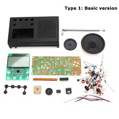
- Basic version:
The processor and display are already soldered to the display PCB. - Improved version:
The SMD version of the processor is supplied separately and you have to solder the 36 mini-contacts yourself on the PCB. You also have to solder the display, which also is not exactly a sinecure. For some reason this version is € 0.40 more expensive than the basic version.
We strongly advise you to order the basic version, especially if you want to make your teenage son or daughter enthusiastic for the electronics hobby. Soldering such an SMD-processor and such a display requires a lot of skill and is nothing for an absolute beginner.
Delivery and parts
Banggood, where we ordered this radio, delivers the kit packed in sloppily sealed black plastic foil as 'shipping box' and with a strip of foam foil as protection. All components are delivered in one plastic bag, which means that the contacts of some components are no longer neatly arranged. However, as always with Chinese retailers, all parts are of excellent quality.
 |
| From these components, you must assemble the FM radio with alarm clock. (© Banggood) |
The entire manual consists of one A4 sheet printed on both sides. On one side is the schematic diagram and the PCB with the component layout, on the other side a table with all the parts you need to solder on the PCB. How to assemble this PCB with the clock PCB, how to mount the buttons, how to put the two PCBs in the box ..... Not a word! It will be clear that this manual is a mockery, especially for a kit that is recommended for starters.
Luckily Banggood has seen that too and you can pick a set of six JPG illustrations from the internet, which better describes the construction of this radio. If you search in Google for images with the search term 'Geekcreit FM Radio Kit' you will find those green images automatically. But even then there are still some assembly steps that are unclear and that will cost you some headaches. But isn't that the charm of building kits?
The end result
The electronics end up in a modern looking black or white box with dimensions 12.0 cm x 7.5 cm x 2.5 cm. A battery compartment is accessible from the rear in which you have to insert two standard type AA 1.5 V cells. At the top there is a antenna which, when extended, is 35 cm long. On the right side there is a knurled wheel to adjust the radio to the stations, on the left there is a similar wheel to adjust the volume and a standard 3.5 mm jack for headphones. Inserting it automatically turns off the built-in speaker. The front has a large display, the power button and five small buttons for setting the alarm clock.
 |
| The radio and alarm clock control buttons. (© 2019 Jos Verstraten) |
To set the current time and the alarm time, push and hold one of the two right buttons and push the left buttons with the other hand to set the minutes and hours. You can only use the 12-hour format, with the indications 'AM' and 'PM' in the display telling you whether you wake up early in the morning or late in the afternoon. These two buttons are in the wrong order. It would have been more logical to set the hour button on the left and the minute button on the right. The 'AL ON/OFF' button enables or disables the alarm function, an action that you can also see in the display by means of a small illuminated symbol.
If you think the alarm function is producing an impressive alarm sound, you are wrong. All that happens is that the radio turns on at the station and the volume you set. Not very useful!
The electronics of the FM-radio
In the figure below you can see the schematic diagram of this radio. The antenna goes to an HF preamplifier around the transistor Q1. The collector signal goes via the capacitor C4 to the input of IC1. The complete radio part is in this IC, a CD2003GP from Wuxi China Resources Semico Co. This allows you to build a combined AM/FM receiver. This IC already works at a supply voltage of only 1.8 V and is therefore ideal for this application. The FM part works with a Intermediate frequency of 10.7 MHz with a maximum swing of ±22.5 kHz. If you would compare the proposed scheme in the datasheet with what is in this radio, you can see that Geekcreit has saved a lot of money. We miss for example a second ceramic bandfilter in the MF part of the receiver, very important for a good quality of reception.
The speaker is controlled from a TDA2822M stereo amplifier from STMicroelectronics. This provides a maximum power of 2 x 120 mW at a supply voltage of 3.0 V. In this radio, the two amplifiers are switched in bridge, from which the specified maximum power of 180 mW can be explained. If you look closely at the diagram, you will notice that this power amplifier is always connected to the 3.0 V supply voltage. However, the idle current from the batteries is only 45 µA, where the current drawn by the clock part is naturally included.
 |
| The full schematic of the radio with alarm clock. (© Geekcreit) |
The clock section is controlled by a SC3610D clock display driver from Hangzhou Silan Microelectronics. This IC is also capable of displaying the frequency to which an AM/FM radio is tuned. This frequency is derived from the frequency of the local oscillator of the radio, point A in the diagram. The chip must only subtract the center frequency of 10.7 MHz from this frequency to display the frequency of the station to which the radio is tuned. The chip has an ALARM-OUT output to which a piezo ceramic buzzer can be connected. In this radio this is unfortunately not used, of course to save a few pennies. Instead, the AL-SIG output is used to supply the FM part with power via the transistor Q2 when an alarm condition occurs.
The clock is controlled from a crystal with a frequency of 32.768 kHz. The diagram shows that no provisions are made to adjust the crystal exactly to this frequency. Every crystal has a certain deviation, so there is a good chance that the clock is slightly ahead or behind.
The technical specifications
The manufacturer provides the following specifications:
- Frequency range: 72 MHz ~ 108.6 MHz
- Intermediate frequency: 10.7 MHz
- Output power: 180 mW max.
- Supply voltage: 3.0 Vdc
Building the FM radio and alarm clock
Assembling the radio PCB
Assembling the radio PCB is the simplest job of construction. Start with the resistors and capacitors. The capacitors are coded with a three-digit number. The first two digits indicate the number of pF, the third digit the number of zeros after the first two digits. A capacitor coded as '472' has a value of 4.700 pF. All supplied resistors have a tolerance of 1 % and have a last ring that is brown in color. Afterwards you can mount the electrolytics flat on the PCB and solder them (pay attention to the plus and minus). Then you solder the three coils and the two ceramic resonators. Pay attention to the number of windings of the three coils: L1 has 5.5 windings, the other two 6.5 windings. The two ceramic filters have no preferred mounting direction. Next you can solder the two transistors and the two IC's, not much can go wrong with that. Finally the larger parts will be installed: the volume potentiometer, the 3.5 mm connector, the on/off switch and the tuning capacitor. Mount the two rotating discs on the potentiometer and the tuning capacitor and the push button on the on/off switch.
 |
| The fully finished PCB of the radio part. (© 2019 Jos Verstraten) |
Next, a job is discussed that requires extreme accuracy: constructing the five buttons on the clock PCB. Instead of using beautiful, sturdy PCB buttons, Geekcreit has opted for an ingenious and very cheap alternative. However, the long term stability of this alternative is extremely doubtful.
As the picture below shows, the switch contacts consist of two copper strips on the PCB. A round contact is in the middle of what the switch should be, this is surrounded by a circular second contact. It is the intention that you glue five flexible metal caps, with two small positioning tabs, over those contacts. You should do this in such a way that absolutely no glue will get under the flexible caps, because then of course the caps move no more when the glue is dry and the switch will not work. You will see two small holes in each circular contact. You can use a pointed object (we used a toothpick) to apply a very small drop of glue to each hole and then carefully insert the flexible cap with the two tabs into the holes. On the picture we have already provided the three left switches with their caps. Next to the two right switches you can see the flexible caps, ready for assembly. After you have glued the five caps to the PCB in this way, you must let them dry for at least a day.
On the left side of the picture you see a plastic strip containing six push buttons. One of these buttons is superfluous, so you have to cut it off. The intention is that you then place the strip in the case, where the five buttons coincide exactly with the five holes in the front plate. The sixth hole will later contain the push button that you have mounted on the on/off switch on the radio PCB.
 |
| The construction of the push buttons is a precision task. (© 2019 Jos Verstraten) |
In the two parts of the casing you should then fit a few mechanical parts. Mount the antenna from the outside using a screw. A soldering tab will be placed under the mounting plate. A second soldering tab is located on the left side of the battery compartment. A tab with a spring contact should be located on the right side of the battery compartment. You can glue the speaker into the housing with a few drops from a glue gun.

The final assembly
The first step is to connect the two PCBs. The package contains a piece of five-core cable that has already been stripped and tinned on both sides. Solder this cable between both PCBs in the holes marked 1-2-3-4-5. Then solder two wires between the speaker and the holes SP1 and SP2 in the radio PCB. Solder two wires between the two tabs of the battery compartment and the PCB holes B- and B+. Solder the last supplied wire to the soldering tab of the antenna, but leave the other side free.
Then screw the clock PCB to the top of the box using two screws. This situation is outlined in the picture below. Now carefully turn over the radio PCB and mount it with four screws over the speaker and the clock PCB. On the copper side of the radio print you will see a copper surface with the inscription 'ANT'. Solder the free end of the antenna wire onto it.
You could now close the housing and secure the back with five screws. Two of those screws are in the battery compartment and they also secure the clock PCB at the bottom. However, you must first test and adjust the radio.
 |
| The mounting of the two PCBs in the housing. (© 2019 Jos Verstraten) |
Fine-tuning the FM receiver
Adjusting the frequency range
Insert two 1.5 V AA type cells into the battery compartment and turn on the radio. If all goes well, you will hear some noise and see a number in the display. This is the frequency the radio is tuned to. Turn the tuning capacitor until the highest frequency appears on the display. Use a screwdriver to twist the copper screw on the radio board marked C1-1 until the frequency 108.6 MHz appears on the display. Turn the tuning capacitor completely to the other side. The display should now show a frequency of 72.0 MHz. If this is not the case, adjust the coil L1 until that frequency appears. This is done by placing a screwdriver between two windings and carefully squeeze out the coil windings. The problem is that you hardly get to this coil. You should repeat both adjustments a few times until the radio covers the range of 72.0 MHz to 108.6 MHz.
The radio in practice
Clock accuracy
As already written, the frequency of the time-determining crystal cannot be adjusted. The tested specimen appeared to have a rather large deviation. At exactly 48 hours the clock was about one minute behind. This means that the clock must often be set equal, rather impractical!
The radio reception
The radio is very sensitive and receives a lot of stations. However, it should be noted that the test was carried out in the Netherlands at 1 km from the German border and that many German stations are received at this location. This is of course not the case in the North Sea area. This great sensitivity is also the problem. Because of the direct coupling between the tuning capacitor and the tuning dial, it is virtually impossible to set the transmitter frequency to an accuracy of 0.1 MHz. Even with the slightest twist of the tuning dial, the tuning frequency jumps by at least 300 kHz and the exact carrier wave of a transmitter is already passed. In short, precisely tuning to the carrier wave of a transmitter is impossible with this radio. If you tune in to a frequency that lies a few 100 kHz next to the carrier wave, then the sound will become terribly distorted and the tuner cannot be enjoyed.
Our opinion on this kit
This kit is advertised as an 'Electronic Learning Suite' for the novice electronics hobbyist. We do not agree, because the assembly requires great care and patience.
The quality of the FM tuner is not what you would expect from a contemporary design. We expect that you use this radio for a short time and afterwards the device will end up in the carton with unusable projects.

Geekcreit FM Radio Kit