|
This function generator kit with an XR2206 is offered for about € 7.00. You will receive a kit of a function generator in a perspex housing with three potentiometers and two jumpers for setting the frequency and waveform. The frequency range goes from 1 Hz to 1 MHz. |
The XR2206 function generator kit
What you get for your money
The assembled kit looks pretty funny. In a perspex box of 55 mm by 72 mm by 32 mm the complete electronics is on one PCB. Top left is a 5.5 mm connector for connecting the power supply, top right a screw terminal with three connectors for the sine/triangular output, the rectangle output and the ground.
In the front plate, which is laser engraved with the necessary texts, two slots are milled. One has a jumper, which allows you to set the frequency in four ranges between 1 Hz and 1 MHz. In the second is a jumper that allows you to set the signal shape to sine or triangle. The rectangle is always available at the second output.
 |
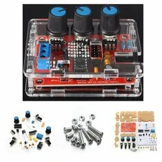
| This will be the result of your tinkering. (© Banggood) |
The manufacturer Geekcreit gives the following specifications:
- Supply voltage: 9 Vdc to 12 Vdc
- Signal shapes: sine, triangle, rectangle
- Output impedance: 600 Ω
- Frequency range: 1 Hz to 1 MHz
- Symmetry: better than 5 % (1 kHz)
- Sine voltage: 3 Vrms maximum at 9 Vdc power supply
- Sine distortion: less than 1 % at 1 kHz
- Sine flatness: 0.05 dB between 1 Hz and 100 kHz
- Peak-to-peak value rectangle: 9 V fixed at 9 Vdc power supply
- Rectangle rise time: less than 50 ns (1 kHz)
- Rectangle fall time: less than 30 ns (1 kHz)
- Triangular voltage: 3 Vrms maximum at 9 Vdc power supply
- Linearity triangle: better than 1 % to 100 kHz
The controls
For seven euros you cannot expect to receive rotary switches to select the frequency and output signal. Geekcreit solved this problem by using cheap jumpers for both settings. With one jumper you set the output signal to sine or triangle, with the other jumper you choose the range of the frequency:
- 1 Hz to 10 Hz.
- 10 Hz to 100 Hz.
- 100 Hz to 3 kHz.
- 3 kHz to 65 kHz.
- 65 kHz to 1 MHz.
With a potentiometer you can set the size of the output voltage for sine and triangle, with two others you can set the frequency of all output signals.
 |
| The controls on the PCB. (© 2019 Jos Verstraten) |
Geekcreit builds this kit around an XR2206CP. This IC was supplied by Exar, a company that has since been taken over by MaxLinear and was known for the production of special linear ICs. The XR2206CP is no longer produced. Apparently there are still large stocks available, because this kit is not the only function generator with an XR2206CP that is offered. The figure below shows the circuit diagram recommended by Exar around the XR2206CP. The IC contains a voltage controlled oscillator VCO, whose frequency is determined by a capacitor between pins 5 and 6 and two resistors to ground on pins 7 and 8. This VCO drives an open-collector transistor, of which the collector is available on pin 11. If you connect this pin with a resistor to the power supply, you can obtain here the rectangular output with a fixed amplitude that is approximately equal to the value of the power supply.
By means of a multiplier and a shaper, the triangular and sinusoidal signals are generated. The DC voltage at pin 3 determines the output amplitude for sine and triangle. A trimming potentiometer between pins 15 and 16 allows you to adjust the symmetry of the signals. Between pins 13 and 14 is a trimming potentiometer that allows you to adjust the sine wave signal to minimum distortion. If there is nothing between these pins, the XR2206 provides a triangle.
 |
| The circuit diagram for the XR2206CP prescribed by the manufacturer. (© Exar) |
Geekcreit adjusts the standard circuit diagram slightly, see figure below. The adjustments have everything to do with the desire to deliver a product as cheaply as possible. What immediately strikes you is that the two potentiometers for adjusting the sine distortion and adjusting the symmetry are missing. The 500 Ω potentiometer for the sine adjustment has been replaced by a 330 Ω fixed resistor. Quite risky when you consider that Geekcreit specifies the maximum distortion on the sine wave at less than 1 % and the asymmetry at less than 5 %.
 |
| Geekcreit's modified circuit diagram saves two adjustment potentiometers. (© 2019 Jos Verstraten) |
The construction of the kit
The manual
The manual consists of one A4 sheet of paper with drawings of the finished PCB and the schematic diagram. You can do the assembly by means of a table, in which each part with colour code or inscription is mentioned.

The quality of the delivered parts
The quality of the parts is excellent. All resistors have a tolerance of 1 %, even an IC socket is delivered. The PCB is also of excellent quality: double sided, through-contacted, with component silkscreen and solder mask. Both sides have a ground plane with a minimum distance between this plane and the tracks. This requires that you solder with a very fine tip. You do have to cut the wires as close to the PCB as possible, otherwise the PCB will no longer fit in the housing (see later).
The housing
There are a few remarks about how to mount the PCB in the housing. The housing is composed of six pieces of perspex, which fit together like a puzzle. These pieces have a protective paper layer on both sides, which is very difficult to remove. First you have to screw the PCB to the bottom plate with the supplied M3x5 bolts. When soldering we had not cut the wires short enough, with the result that the bolts had to be replaced by 10 mm copies and insulating washers had to be placed between the bottom plate and the PCB to prevent the bottom plate from warping. Then insert the four sides into the grooves of the bottom plate, snap the top plate into the four side plates and screw everything together using the four M3x15 bolts supplied. At least, that's how Geekcreit came up with it, but it doesn't work that way. The intention is to screw the M3x15 bolts as self-tapping screws into the small holes of the bottom plate. We didn't succeed. There is only one solution: drill the holes in the base plate to 3 mm and work with M3x20 bolts with nuts. Then the next problem arises. The side plates are 11 mm high, which is two millimetres too little. If you do not cut all wires short enough, the PCB will fit with no possibility in the 11 mm space between the bottom and top plate and will bulge when you tighten the four bolts.
 |
| From these six perspex plates you have to assemble the housing. (© Banggood) |
These are some of the things we do not understand. Are such kits not tested by the manufacturer? Correcting these shortcomings by making the side plates slightly higher, providing longer bolts and eight instead of four M3 nuts might have increased the price of this kit by half a euro.
Testing the XR2206 function generator
Test conditions
We powered the device from a stabilized 12 V mains power supply. The oscilloscope images were made using a DSO5102P digital scope from Hantek. Both outputs are terminated with resistors of 10 kΩ.
Performance at 1 kHz
First we put the triangle, sine and rectangle outputs at 1 kHz on the scope. With the amplitude potentiometer fully open, both the sine and the triangle are clipped against the supply voltage. This potentiometer has to be turned back considerably before the device delivers completely undistorted sine waves and triangles. The peak-to-peak value of the undistorted voltages:
- Rectangle: 10 V.
- Triangle: 6.56 V (2.3 Vrms).
- Sine: 5.56 V (2.00 Vrms).
What is striking is that the lower part of the rectangle is not at 0 V, but at 1.16 V. Apparently the 1 kΩ resistor connected to the open-collector transistor is too small, so that the voltage across the conducting transistor remains at 1 V. Exar advises a resistor of 10 kΩ at the location. The lower points of the triangle will stick at 1.40 V, the lower points of the sine at 2.88 V. So, to remove the DC voltage from the signal, it will be necessary to apply the output voltage of this function generator to a circuit via a capacitor.
 |
| The triangle, sine and rectangle at 1 kHz. (© 2019 Jos Verstraten) |
Every low-frequency function generator, no matter how cheap, must deliver usable signals up to 20 kHz. That is why we have performed the following test at this frequency. As the picture below shows, this is not disappointing. The three generated signals can be used in the hobby laboratory. What does stand out is that it is not easy to set the frequency exactly to a desired value with the two potentiometers.
 |
| The triangle, sine wave and rectangle at 20 kHz. (© 2019 Jos Verstraten) |
With both frequency potentiometers fully turned open, the tested circuit delivers signals with a frequency of 1.23 MHz. As the picture below shows, the rectangle is of course quite distorted and there is no difference between sine and triangle output. That is why we only took one screenshot.
 |
| The performance at the very highest frequency of 1.23 MHz. (© 2019 Jos Verstraten) |
There is a design error in the PCB. By default, an amplitude potentiometer delivers more signal if you turn it clockwise. This is not the case with this circuit, it works the other way around. Moreover, it does not control from 0 V, as you would expect, but from about 0.18 Vrms. A minimum output voltage of 180 mV is of course far too large for a lot of applications, so you will often have to work with an external voltage divider to get a usable output voltage.
The rise and fall times of the rectangle
We measured the rise and fall times of the rectangle pulse. These were about double the specified values:
- Rise time: 118 ns.
- Fall time: 77 ns.
That the fall time is much shorter than the rise time can be explained by the open-collector functioning of this output of the XR2206. When the transistor is driven in conduction, the output immediately goes to zero. When driving the transistor to cut-off, the output voltage must build up via the 1 kΩ resistor and that takes a while.
In any case, these values are small enough to drive fast digital ICs without any problems. It is a pity of course that there is no amplitude control present and that you have to work with an external resistor divider if you want to control TTL-ICs with this function generator.
 |
| The rise and fall times of the rectangular output voltage at 1 kHz. (© 2019 Jos Verstraten) |
Finally, we examined the accuracy of the five frequency ranges:
- 1 Hz to 10 Hz: measured 0.7 Hz to 23 Hz
- 10 Hz to 100 Hz: measured 7 Hz to 217 Hz
- 100 Hz to 3 kHz: measured 155 Hz to 4.6 kHz
- 3 kHz to 65 kHz: measured 3,2 kHz to 92,5 kHz
- 65 kHz to 1 MHz: measured 52,7 kHz to 1,2 MHz
Our opinion on this kit
Contra
In order to be able to offer a function generator at an absolute bottom price, Geekcreit has made many compromises that cause a lot of limitations for the device. Especially the amplitude control with a wrong direction potentiometer and a control up to only 180 mV makes this generator unsuitable for work in the hobby lab. To do something useful with this device, you need to add a good external amplitude control that controls in the right direction from 0 V to maximum, and preferably is extended with a 1/10 and 1/100 step attenuator, so you can also generate signals of a few millivolts.
Pro
A separate XR2206 is sold by for example Reichelt Elektronik for EUR 5.85. That's about the same amount of money you have to pay Chinese suppliers for the complete kit. The separate electronic components are therefore worth more than the price you have to pay for this kit.

XR2206 Function Signal Generator DIY Kit