|
The GLPS1502C is one of the cheapest linear power supply you can buy. With its voltage up to 15 V and current up to 2 A, this power supply is an excellent entry-level model for the hobbyist. Whoever claims that Chinese people cannot make excellent cheap products should read this test! |
Introduction to the GLPS1502C from Geti
Confusion about manufacturer and type
If you search for the term 'lab power supply' via Google, this power supply not only stands out because of its low price of approximately € 45.00, but also because only two Dutch suppliers are found: Eleshop and Soldeerbout-Shop. Moreover, there is quite some confusion about manufacturer and type number. Eleshop, where we bought our test sample, does not mention any brand and type number. However, the picture on the product page clearly shows the brand 'MCI Power' and the type number 'NG-1620BL'. However, the supplied device has 'Geti' as the manufacturer and 'GLPS1502C' as the type number. Moreover, an identical power supply is also available as 'HY1502D' from the brand 'Mastech' and as 'QJ1502C' from the brand 'QJE'.
Fortunately, the nameplate on the back of our power supply brings some clarity. The power supply is made in China and is manufactured by the company 'Ningbo JiuYuan Electonic Co' (http://www.nbjiuyuan.cn/). 'Geti' turns out to be a brand name of the Czech importer Tipa.
Because we have received a GLPS1502C we have named this article as well. However, you can almost be sure that this test also applies to the HY1502D, the QJ1502C and the NG-1620BL.
Why buy a linear power supply right now?
The Geti GLPS1502C is an adjustable laboratory power supply with a voltage range from 0.0 V to 15.0 V that can deliver a maximum current of 2.0 A. The power supply works according to the 'old-fashioned' principle of linear control.
Most modern laboratory power supplies work switched according to the buck-principle or the pwm-principle. Both systems work in switched-mode, where the high unstabilized DC voltage at the input of the control system is chopped into narrow sections by a fast semiconductor switch. The narrower the sections, the lower the output voltage. The result is smoothed. Both systems work very efficiently, little power is lost in the power supply. However, the disadvantage of both systems is that a lot of residual switching frequency appears on the output.
You don't have that problem with a linear power supply. It does not switch, but uses a transistor as a variable resistor between the unstabilized input voltage and the output of the power supply. The linear control has the advantage that there is a (in theory) absolutely pure DC voltage on the output. The disadvantage is that a lot of power is dissipated in the circuit, a lot of heat is dissipated through a large heatsink.
In the figure below, the three basic principles of a lab power supply are compared.
 |
| We compared the three principles with which power supplies can work. (© 2020 Jos Verstraten) |
The power supply comes in a sturdy metal housing measuring 22.5 cm deep, 15.0 cm high and 9.5 cm wide. The front of the housing is made of plastic and contains two single-turn potentiometers for adjusting the output voltage and the output current, two LEDs, two three digit digital LCD meters, an on/off switch and two 4 mm connectors. As can be seen in the picture below, the two digital meters have a nice green backlight when the power supply is switched on. It is a pity that the viewing angle of the LCD's is not very large. If you look at the power supply at a not even sharp angle, the segments of the displays will fade.
The green LED lights up when the power supply provides a constant voltage, the red LED lights up when a constant current is available.
With its 2.015 kg, the device is certainly not a lightweight. This is a logical consequence of the linear operating principle that requires a heavy 50 Hz transformer and a heavy heatsink. This heatsink takes up almost the entire back of the housing. Under the heatsink is a fuse holder and the cable entry for the thick power cable with a length of just over one meter. This cable ends in a sturdy earthed mains plug.
Besides the power supply, two small cables are supplied with banana plugs on one side and crocodile clips on the other side. A short manual in English, Czech and Polish is also included.
 |
| The appearance of the GLPS1502C. (© 2020 Jos Verstraten) |
It should be noted that the earth of the mains plug is connected to the metal housing, but not to the black 4 mm connector. A lot of power supplies have a third output connector which is connected to chassis and with which you can earth the positive or negative output by means of a metal clamp. With this power supply you have to do this with a cable.
The specifications according to the manufacturer
According to the manufacturer, the GLPS1502C has the following technical specifications:
- Input voltage: 220 Vac ± 10%
- Output voltage: 0 Vdc ~ 15.0 Vdc
- Output current: 0 A ~ 2.0 A
- Output hum and noise: less than 5 mV
- Voltage regulation: better than 10-4 ±3 mV
- Current regulation: better than 10-3 ±6 mA
- Voltage meter accuracy: 1 % ±1 digit
- Current meter accuracy: 1 % ±1 digit
The electronics in the GLPS1502C
Opening the housing
The housing of this power supply consists of a U-shaped base on which the electronics are mounted and a U-shaped cover that is attached to the base with eight small screws. So it takes little effort to take a look at the electronics of this device. The amazingly small transformer is mounted on the base plate. Even more amazing is that this transformer has no less than four secondary windings. The circuits around the digital meters are apparently powered from completely separate supply voltages.
On the back there is a PCB on which the rectifier, smoothing capacitor and stabilization electronics are mounted. This board is screwed directly onto the heatsink. On this PCB is a relay, which offers two different transformer voltages to the rectifier (read further).
Behind the front is a large PCB that contains the electronics of the two digital meters and the control electronics for setting the constant voltage or constant current. The two output connectors are mounted on a small third PCB, which also contains the current sensor resistor.
 |
| The interior of the GLPS1502C seen from the front. (© 2020 Jos Verstraten) |
 |
| The interior of the GLPS1502C seen from the rear. (© 2020 Jos Verstraten) |
Although the wiring has been installed rather sloppily in the interior of the device, details still show that the manufacturer did not make it a rush job. Solder connections are insulated with heatshrink tubing, all PCB connectors are fixed with a drop of glue and all wires carrying the mains voltage are additionally insulated with pieces of tubing. Even the primary smoothing capacitor of 3,300 µF is glued to the PCB.
The two LCD's are controlled by Chinese clones of the well-known Intersil digital voltmeter chip ICL7106. The two meters measure the real output voltage and the real output current provided by the power supply.
Under the rear PCB, a TIP3055 transistor is screwed to the heatsink. This transistor is mounted isolated, the heatsink is voltage-free.
The output PCB
The two output connectors are not mounted on the front panel, but on a small third PCB, see the picture below. On this circuit board there are also a few parts, like the output filter, the reverse diode between the output terminals and a wirewound resistor that is probably the current sensor. The two connectors are not screwed to this circuit board, but soldered. We don't think this is the best solution. After all, when plugging in banana plugs, a lot of force is applied to the connectors, and that does not seem to be beneficial for the solder connections.
 |
| The output PCB with the two 4 mm connectors. (© 2020 Jos Verstraten) |
The Geti GLPS1502C on the test bench
Maximum voltage and current
Our specimen delivers a maximum voltage of 16.3 V and a maximum current of 2.28 A.
Switching from low to high unstabilized voltage
As already described, the GLPS1502C works with two transformer voltages. With a low output voltage a low transformer voltage is offered to the rectifier, with a high output voltage a high one. In this way, the maximum power wasted by the TIP3055 is limited.
In our specimen, the relay switches at an output voltage of 4.2 V. The low unstabilized voltage is unloaded 13.2 V and with a 2 A load 10.35 V. The high unstabilized voltage is unloaded 24.5 V and with a 2 A load 18.9 V. This is measured at a mains voltage of exactly 230 Vac.

Voltmeter accuracy
In the table below we have summarized the accuracy of the built-in voltmeter. Because the resolution of this meter is only ±100 mV, an inaccuracy occurs when setting the output voltage. We have very slowly turned the potentiometer from a low to a higher voltage and measured when the built-in meter started to indicate the desired value.
As the table shows, the accuracy of the voltmeter is excellent.
 |
| The accuracy of the built-in voltmeter. (© 2020 Jos Verstraten) |
In the same way, we measured the accuracy of the built-in ammeter and there is nothing to complain about.
 |
| The accuracy of the built-in ammeter. (© 2020 Jos Verstraten) |
We have set the output voltage to 5.00 V and 15.0 V and loaded the power supply with a digitally adjustable current source. The table below shows the decrease of the output voltage, measured relative to an unloaded output. A maximum voltage drop of 10 mV occurs over the internal resistance of the power supply at a load of 2.0 A. With Ohm's law, you can then calculate this internal resistance as 5.0 mΩ. An excellent value!
 |
| The output stabilization at 5.00 V and 15.0 V. (© 2020 Jos Verstraten) |
In the introduction we wrote 'The linear control has the advantage that there is a (in theory) absolutely pure DC voltage on the output.', with the emphasis on 'in theory'. In practice you will also measure some unwanted signals at the output voltage of a linear power supply. In the first place ripple, a remnant of the 50 Hz AC voltage with which you power the device. Secondly, noise, because every electronic circuit generates noise.
Here too, the GLPS1502C performs very well. In the oscillogram below you can see the ripple and noise on the output voltage of 5.00 V with a load of 2.0 A. Note the sensitivity setting of the oscilloscope: 1 mV/div! There is no ripple at all on the output voltage, only a very small noise voltage. Measured with our Philips PM2454 AC millivoltmeter with a bandwidth of 2 MHz, our test device provides 0.42 mVrms noise at 5.00 V output voltage and 0.95 mVrms noise at 15.0 V output voltage. Note that both voltages were measured at the maximum load with 2.00 A.
 |
| The ripple and noise on the output at 2.00 A load. (© 2020 Jos Verstraten) |
The mains voltage can fluctuate quite a bit over the period of half a day. If you use the GLPS1502C in a measuring setup, fluctuations on the mains voltage should not affect the output voltage of the power supply. This specification is expressed by the term 'input stabilization'. We have connected our test device to a variac set precisely to 230 Vac, set the output to 15.0 V and loaded the power supply with 2.00 A. Afterwards we varied the simulated mains voltage between 210 Vac and 240 Vac. In the table below you can see the deviation of the output voltage with respect to the value at 230 Vac.
That could have been better! When the mains voltage drops from 230 Vac to 220 Vac, a drop of only 4.3%, the output of the power supply already starts to notice that. Fortunately, this phenomenon only occurs at a load of 2.00 A. At a current of 1.80 A, the output voltage remains stable in the fully measured range. With an output voltage of 5.00 V there was no sign of a voltage drop, not even with a load of 2.0 A.
 |
| The input stabilization at 15.0 V and 2.00 A. (© 2020 Jos Verstraten) |
 |
| The ripple at 15 V at a mains voltage of 210 Vac. (© 2020 Jos Verstraten) |
One of the typical characteristics of a linear power supply is that the device becomes quite warm if you load it with a large current for a long period of time. There are two heat sources: the transformer and the regulating transistor on the heatsink. Both parts quickly become quite hot. If you use the power supply for a long time at full power, the heat spreads through the device and everything heats up. But the intention is that even then the power supply will continue to work perfectly and generate stable output voltages. We tested this by setting the power supply to 8.00 V and loading it with 2.00 A. Afterwards, we measured the output voltage and the temperatures of the transformer and the heatsink every quarter of an hour. As the table below shows, the GLPS1502C meets all the requirements you can set in this area. The maximum temperature of 60 °C does not pose a threat to the long-term operation of the device.
 |
| Measuring the long-term stability. (© 2020 Jos Verstraten) |
All tests carried out are static tests, as the power supply is always loaded with a constant current. In practice, however, a power supply will often have to supply rapidly varying currents. Just think of an application in which you use the power supply to power a heavy switching circuit. It is therefore important to test the dynamic behaviour of a power supply. We have carried out the following experiment for this purpose. The GLPS1502C is set to 5.00 V and connected to a 4 Ω resistor. However, between this resistor and ground, a 2N3055 transistor is connected, which is driven in the base with a square wave with a frequency of 1 kHz. The GLPS1502C has to switch from no-load to a load of about 1 A (and vice versa) a thousand times per second. Of course, the oscilloscope is used to measure the signal at the output of the power supply.
When the transistor switches, narrow peaks of 25 mV occur on the power supply voltage provided by the GLPS1502C. This is an acceptable value.
 |
| A dynamic test of the GLPS1502C. (© 2020 Jos Verstraten) |
Our opinion on the Geti GLPS1502C
It must have become clear from this article that we are quite enthusiastic about this power supply. The GLPS1502C passes most of our tests with flying colours. The only test that is slightly disappointing is that of input stability at an extremely low mains voltage of 210 Vac. You will not often encounter this situation in practice. We only have one wish, although we realise that this wish will increase the price by at least ten euros: perform the output voltage adjustment with a double potentiometer (concentric potmeter). Outer potentiometer: coarse adjustment, inner potentiometer: fine adjustment.
We warmly recommend this power supply to every hobbyist who wants to expand his or her lab with a good, reliable power supply.

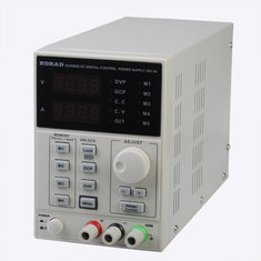
KA3005D, lab power supply 30 V - 5 A