|
With this very simple circuit you can demonstrate and experiment with the principle of levitation by means of ultrasonic standing waves of 40 kHz. |
What is ultrasonic levitation?
Sound is caused by pressure differences in the air
As you undoubtedly know, sound is caused by pressure differences between the molecules that are present in the air. Those pressure differences move through the air at a speed of about 343 meters per second, or 1,234.8 kilometers per hour. Note that it is not the molecules in the air that move, but only the pressure differences between these molecules. This is shown in the drawing below. On the left is a loudspeaker that is powered by an AC voltage. As a result, the speaker cone vibrates back and forth. When the cone moves to the right, the molecules in the air are locally compressed. At that point, an area of high pressure is created. The speaker cone creates a force that moves the pressure wave to the right. When the cone moves to the left, the molecules are locally pulled apart. An area of low pressure is created. The pressure waves move in total from left to right. We receive these pressure waves in our ears and they make our eardrum (tympanic membrane) vibrate.
 |
| The origin of pressure waves in the air. (© 2022 Jos Verstraten) |
The origin of standing waves
What happens if you line up two identical speakers perpendicularly with the cones facing each other and feed both voice coils with the same signal? The top loudspeaker sends pressure waves downwards, the bottom loudspeaker sends identical pressure waves upwards. At a specific distance between the two loudspeakers and at certain signal frequencies, so-called 'standing waves' are created between the two loudspeakers. The high pressure and low pressure zones of both loudspeakers coincide exactly and amplify each other. A static pressure distribution of areas of low pressure and areas of high pressure is then created between the two speakers.
The locations at which the pressure is minimum are called 'nodes', the locations where the pressure is maximum are called 'antinodes'. The space between the two loudspeakers is called the 'cavity space'.
If you now carefully place a very small and light object, for example a small piece of polystyrene foam, in a zone with the lowest pressure, there is a good chance that this object will float in that place. After all, the nearby areas with a high pressure exert two identical forces on the object and these forces are many times greater than the force exerted by gravity on the object. Both forces work in opposite directions, the object has no force and, as Newton already knew, a stationary object, on which no force is exerted, remains stationary.
The piece of styrofoam remains floating in the air between the two speakers!
 |
| The origin of standing waves. (© 2022 Jos Verstraten) |
Levitation
According to the Dutch Dictionary, the definition of levitation is 'a phenomenon or condition in which someone or something is pulled from gravity and floats, either in a physically explicable manner or allegedly by psychic or supernatural forces'. Floating under the influence of the forces of sound pressure is thus a typical example of levitation.
Ultrasonic levitation
In practice, ultrasonic sound waves are usually used with a frequency around 40 kHz. The first reason is that it takes a lot of acoustic power to make even the lightest objects float. If one were to use audible sound, this would not be very hearing-friendly because of the necessary high volume.
The second reason has something to do with the desired wavelength. The distance between two consecutive nodes or two consecutive antinodes is equal to half the wavelength of the applied sound. To achieve the high sound pressure, it is necessary that the two speakers are not too far from each other. Sometimes that distance is only a few centimeters. In order to get a few nodes in that small distance, it is necessary that the wavelength of the applied sound is smaller than 1 cm. The wavelength of a sound wave with a frequency of 40 kHz is approximately 9 mm in the air and is therefore well usable.
But that 40 kHz is very suitable for another reason...
Ultrasonic transducers with resonance at 40 kHz
Speakers are completely unsuitable for reproducing sound with a frequency of 40 kHz. The mass of the cone is much too large and the elasticity much too small. Fortunately, so-called piezoceramic transducers have been around for decades. With such parts, a slice of a specific material is connected to an alternating voltage. The result is that the slice starts to vibrate. The mass is minimum, the elasticity is maximum. Apparently it is very simple and also very cheap to make such a transducer with a resonance frequency of 40 kHz. Such parts were formerly used in parking aids, remote controls, intrusion detectors and in devices for measuring distances.
It will be appreciated that these transducers are ideal for experimenting with the phenomenon of 'ultrasonic levitation'. In the photo below you can see what a Chinese transducer looks like. This is model MSO-A1640H10T from Manorshi Electronics with a resonance frequency of 40.00±1.00 kHz and a maximum output of 110 dB. The dimensions of the housing are 10 mm by 16 mm, you pay only € 0.78 for two pieces via AliExpress.
 |
| The ultrasonic transducer MSO-A1640H10T. (© Manorshi Electronics) |
The TinyLev
The idea of ultrasonic levitation is not new. As early as 1866 Kundt conducted such experiments to determine the speed of sound in various media. Also at NASA there was a lot of experimentation with the phenomenon to study the behavior of liquid droplets on Earth in a virtually gravity-free state.
However, such setups were very elaborate and expensive and unsuitable for the hobbyist. That changed with the public publication of the 'TinyLev' design. This ultrasonic levitator consists of two parabolic dishes packed with a total of 76 ultrasonic transducers. Due to the parabolic construction, the sound waves are bundled in the focal point of the two dishes. This is where strong standing waves are created and small objects can be made to float.
Building kits of the TinyLev are offered by Elektor and AliExpress, among others. You pay around a hundred euros for it, which is quite an amount for a toy with no practical applications.
 |
| The design of the TinyLev. (© Researchgate, edit 2022 Jos Verstraten) |
The cheap alternative?
However, if you google for the term 'ultrasonic levitator', you will discover that DIY kits are offered via AliExpress and Banggood for about € 15.00. The strange thing is that these use only two ultrasonic transducers that radiate their acoustic energy to each other without any acoustic beamforming. In the photo below we have presented two popular versions. If you compare these devices with the TinyLev, it seems unlikely that such simple designs generate enough acoustic energy to make something float, even if it is just a piece of Styrofoam.
That is why we have ordered a copy of the kit on the right and in this article we describe our experiences with it.
 |
Two versions of the cheap kit. (© 2022 Jos Verstraten) |
The GY20451 ultrasonic levitator kit
Manufacturer, suppliers and prices
The kit purchased by us has the type number GY20451 and has an unknown manufacturer. When studying the photos on the various webshops, it is clear that there are a number of versions of this design on the market. Those models do not differ fundamentally, but in some details such as the number of indicator LEDs and the type of voltage stabilizer. The model we tested is available at Banggood under product code 1962118 for € 15.46. At AliExpress, this kit seems considerably cheaper, but you have to take into account shipping costs of up to € 6.00, making the total price about the same.
The performance
If we are to believe the videos on AliExpress, the cheap GY20451 does much the same as the much more expensive TinYLev: make small pieces of Styrofoam float. As an example, we publish part of a video that is on an AliExpress page. Notice how pieces of this material are gently applied to four nodes of the standing waves between the two transducers.
The delivery of the package
As is unfortunately usual with cheap Chinese deliveries, the parts are compressed in a plastic bag that is too small. It is worth noting that this kit uses very small SMD components. Soldering these millimeter-sized parts on the PCB requires quite a bit of experience, good eyes and steady hands! This kit is therefore not suitable as a first introduction to soldering electronic parts.
 |
| The delivery of the kit. (© 2022 Jos Verstraten) |
The components of the kit
In the photo below you can see what you get for your fifteen euros. The three round PCBs form the 'housing' of the circuit. Only the electrolytic capacitor is supplied as a radial component, the rest is all SMD. The brass spacers not only ensure the mutual distance between the three PCBs, but also transport the control voltages for the ultrasonic transducers to these parts.
 |
| The components of the kit. (© 2022 Jos Verstraten) |
The technical specifications
According to the supplier, the GY20451 has the following specs:
- Supply voltage: 12 Vdc
- Supply current: 70 mA
- Indicator: blue LED
- Cavity space: 15 mm
- Dimensions: 40mm x 40mm x 64mm
- Weight: 27g
The building description
A building description is of course not included, but it can be found on the internet. It is true that this document describes a slightly different version, but in general you can get started with it. We have saved this manual for you in our cloud on Google drive:
➡ GY20451_Manual.pfd
The electronics of the GY20451
The version of the GY20451 supplied to us contains only ten electronic parts. Thus, the scheme is quickly reconstructed and worked out in the illustration below.
The 12 V supply voltage is converted into 5 Vdc in U1, an AMS1117, to power the microcontroller. Both the input and output of this stabilizer are decoupled with capacitors C5, C1 and C2. LED1 is connected to the 5 V output via the series resistor R1.
An STC15W104 is used as microcontroller. It has a built-in clock generator, so no external parts are necessary in this scheme. Two square waves with a frequency of 40 kHz appear at the outputs P3.2 and P3.3.
These two signals drive the two inputs of U3, a TCA4427. That is a double 'High-speed Power MOSFET Driver'. The outputs are connected by means of two MOSFETs either to ground or to the 12 V power supply. These two outputs directly feed the two piezoceramic resonators TX1 and TX2.
 |
| The schematic of our version of the GY20451. (© 2022 Jos Verstraten) |
Maximum acoustic power from 12 V
The power supply of the resonators is very cleverly conceived. By powering these components from the two inverted outputs of the TCA4427, a kind of bridge circuit is created that extracts the maximum acoustic power from the 12 V supply. This is explained in the figure below.
In one state (red), the top terminal of the transducer is connected to +12 Vdc and the bottom terminal to ground GND. A current flows in one direction through the transducer. The crystal in the transducer expands and creates an area of maximum sound pressure. In the other state (blue), the top terminal of the transducer is grounded and the bottom terminal is connected to +12 Vdc. Current flows in the opposite direction through the transducer. The crystal in the transducer shrinks, creating an area of minimal sound pressure.
 |
| The powering system of the transducers. (© 2022 Jos Verstraten) |
Building the GY20451
Soldering the basic PCB
The figure below shows the components on the basic PCB. You can start by soldering the one resistor R1 and the two capacitors C1 and C2. Cover one of the pads on the PCB with a thin layer of solder. Under a magnifying glass, place the SMD with tweezers centrally between the two pads and add a little solder from the tip of your soldering iron to the already tinned pad. You can see the solder melting and making the connection between the tinned end of the part en de PCB pad.
 |
| The silkscreen of the basic PCB. (© 2022 Jos Verstraten) |
Then solder the second pad of the part. Inspect the solder joints under the magnifying glass. The solder must have flowed well to the tin-plated parts of the parts.
 |
| Soldering an SMD resistor. (© Tomislav Darlic) |
You can then solder LED1 to the PCB in the same way. Note, however, that such an LED has an anode and a cathode and that you should not mix them up. The LED has two green dots and you have to align these on the PCB as shown below.
 |
| The position of the LED on the PCB. (© 2022 Jos Verstraten) |
Afterwards it is the turn of the AMS1117. You should not only solder this chip on the three narrow pads on the front, but also on the slightly larger pad on the back. Now you need to solder the STC15W104 and the TCA4427. Note that the position of these two chips is not identical, see the position of the marking next to pin 1! Also with these chips you start with tinning a corner path. Then position the chip properly on the PCB with the tweezers and let the solder make the connection between the pad and the pin of the chip. Afterwards you can solder the other seven pins. Finally, solder the electrolytic capacitor C5 (note the plus and minus) and the power connector on the PCB.

The final assembly of the GY20451
Then solder the two ultrasonic transducers to the two remaining round PCBs. Make sure that both parts are soldered to the PCBs in the same way!
 |
Mounting the ultrasonic transducers. (© 2022 Jos Verstraten) |
Finally, screw the three PCBs together with the brass spacers. Pay attention to the pluses and minuses on the three PCBs! The four shortest spacers are used as legs under the basic PCB.
 |
| The fully assembled GY20451 connected to a mains plug supply. (© Banggood) |
Testing the GY20451
Does he work or does he not work?
We were quite skeptical. Twelve volt supply at 70 mA current means a power consumption of only 0.84 W. Is such power (minus the power loss in the circuit) capable of making something, even a piece of Styrofoam, levitate? It didn't seem like it, because our GY20451 wouldn't let anything float.
A faulty TCA4427
In such a case the oscilloscope is switched on. The STC15W104 delivers two nice inverted square waves with a frequency of 39.29 kHz. These signals also appear on the two inputs of the TCA4427. However, this chip produces two remarkable output signals that look nothing like voltages that switch between 12 V and 0 V. After a thorough check of the soldering around the TCA4427, no errors appear to have been made. The ground and the power supply can be found on the pins of the chip, as well as the input signals. We can only conclude that the delivered TCA4427 is defective or has become defective due to soldering for too long.
 |
| The output voltages of the STC15W104. (© 2022 Jos Verstraten) |
We are still experimenting!
Of course we do not have an SMD version of the TCA4427 in stock. End of the experiment? This is not necessary, because we can also offer a square wave with a frequency of 39.29 kHz to the two ultrasonic transducers with our function generator. It is true that this device delivers a peak-to-peak voltage of 20.0 V maximum and that will have slightly less effect than the 12 V that is offered to the transducers via bridge circuits. But it's worth a try.
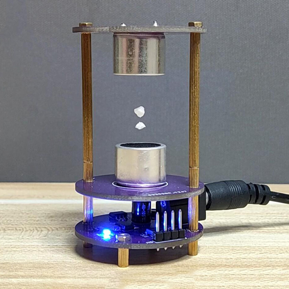
It functions! You can see the proof in the photo below! We are able to float a small piece of styrofoam in the cavity between the two transducers. There are two positions where this works. So those are the two nodes of the standing waves produced by the transducers.
 |
| With the 20 V of our function generator we can do float one small piece of styrofoam. (© 2022 Jos Verstraten) |
Some more experiments
Now that we are freed from the fixed frequency and amplitude of the circuit, we have of course tested how far the frequency can deviate. At 20 V peak-to-peak, the styrofoam floated between 37.8 kHz and 40.1 kHz. Considering this as 'bandwidth' and assuming that this is a normal Gaussian distribution, the transducers can be expected to deliver the most power at 38.95 kHz. That turned out to be the case. At this frequency, the amplitude of the signal can decrease to 13.5 V before the styrofoam falls.

Ultrasonic Levitator Kit