|
For just over € 1.50 you buy this motion sensor. You can detect every movement within a radius of up to seven meters. When motion is detected, the output becomes 'H', that allows you to control a lamp or alarm in a very simple way. |
Introduction to the HC-SR501
What is a PIR sensor?
A PIR sensor does not work according to the radar principle, but detects moving objects that are warmer or colder than the environment. A PIR sensor is in fact nothing more than an extremely sensitive infrared detector, which detects even the slightest deviation in the infrared radiation field.
The PIR sensor HC-SR501
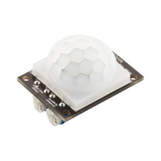
Like any PIR sensor, Shenzhen Jieshen Technology's HC-SR501 is characterized by the typical dome, the fresnel lens that the PIR sensor needs to detect the varying infrared radiation of moving people. The entire circuit is located on either side of a PCB with dimensions of 32 mm by 24 mm. At the bottom you will see two adjustment potentiometers. One allows you to set the range between about three and seven meters, the other allows you to set the time that the output remains 'H' after detection. The range is from five seconds to five minutes. You must power the module from a DC voltage between 5 V and 20 V.
 |
| The PIR detector HC-SR501 from Shenzhen Jieshen Technology. (© Banggood) |
In the picture below we have removed the fresnel lens, so that the actual PIR sensor becomes clearly visible. This is a type RE200B from Glolab Corporation. This may be powered up to 4.0 V, hence the circuit has a stabilizer to 3.3 V present. On the other side of the PCB you can see the heart of the circuit, a BISS0001 chip from Shenzhen Fuman Electronics Co which is specially developed for processing the signals from a PIR sensor. In addition, there is the stabilizer that reduces the supply voltage to 3.3 V. Below left is a jumper, with which you can set the triggering of the module.
Below the connector you see two contacts 'RL'. If you wish, you can solder an LDR in these contacts, so that the module takes the intensity of the ambient light into account. If you apply this light-sensitive resistor, the module will not react in daylight. This is an ideal option if you want to use the HC-SR501 to control a lamp that only lights up when it is dark and when someone approaches. Unfortunately, you cannot set the sensitivity of this option.
Next to the sensor are two contacts 'RT'. Here you can solder a thermistor, which makes the sensitivity of the PIR sensor less dependent on the ambient temperature. Unfortunately we have not found any further information about the type and value of this thermistor.
 |
| The two sides of the PCB, with removed fresnel lens. (© 2018 Jos Verstraten) |
In the figure below we have shown the complete scheme of this module. At least ... one version of the module, because as is unfortunately often the case with Chinese products, there are several versions of the HC-SR501 in circulation, with a slightly different wiring diagram and slightly different print layout.
On the far left you see the PIR sensor. The output goes to pin 14 of the BISS0001. That is the input of the first amplifier in this IC. Between pins 14/15/16 and 13/12 you will find two operational amplifiers, which amplify the very small signal from the PIR sensor. The potentiometer RL2 is included in the feedback of the second op-amp and controls the sensitivity and therefore the range of the circuit.
 |
| The wiring diagram of one version of the HC-SR501 module. (© S-J Tech) |
In case you are wondering how it is possible that this module is offered for so little money, we will give you a sneak preview. The BISS0001 is for sale for the price of $0.0965.
 |
| The internal block diagram of the BISS0001. (© Shenzhen Fuman Electronics Co) |
- Price indication: from € 1.33
- Manufacturer: Shenzhen Jieshen Technology
- Supply voltage: 4.5 Vdc to 20 Vdc
- Quiescent current: less than 50 μA
- Active output signal: 3.3 V
- Sensor opening angle: 100 °
- Fresnel lens diameter: 23 mm
- Detection range: 3 m to 7 m adjustable
- Output pulse: 5 s to 300 s adjustable
- Operating temperature: -15 °C to +70 °C
- Dimensions: 32 mm x 24 mm
The operation of the HC-SR501
After switching on the power supply, the output of the module is unreliable for three seconds. After wards the output goes to 'L' if no movement is detected. When a movement is detected, the output goes to 'H' and remains at this level for an adjustable time. After the set time has elapsed, the output goes back to 'L'. For the next three seconds the output will remain 'L' under all circumstances, even if a movement is detected.

Setting the trigger jumper
With this jumper you can select the mode of the module.
- Single trigger:
The output pulse starts immediately after a movement is detected and remains 'H' until the set time has elapsed. If during this time other motion detections occur, they have no influence. - Repeatable trigger:
Every new movement detected starts a new time cycle.
 |
| The difference between 'single trigger' and 'repeatable trigger'. (© 2018 Jos Verstraten) |
Example circuits with the HC-SR501
The simplest application
The figure below shows the simplest application with this module. The output of the HC-SR501 directly controls the base of the transistor T1. A basic resistor is not necessary, it is on the PCB. In the collector is a relay coil and the diode D1 which suppresses the opposite voltage of the coil.
 |
| The output of the module controls a relay via a transistor. (© 2018 Jos Verstraten) |
If you use the following circuits, pay close attention when working with the life-threatening mains voltage!
230 V lamp switching
In practice, you often want to switch a 230 V lamp with a motion sensor. The figure below shows how this can be done most easily. The mains voltage is rectified by four 1N4007 diodes and a thyristor short-circuits this bridge rectifier when a movement is detected. This short circuit connects the La1 lamp to the mains voltage and lights up. The disadvantage of this system is that the HC-SR501 is powered by three 1.5 V batteries. Because the power consumption of the module is very low, less than 50 μA, this does not have to be a problem.
 |
| Switching a 230 V lamp with the HC-SR501. (© 2018 Jos Verstraten) |
Finally, a circuit where you don't need those batteries. The power supply for the module and the external electronics is now taken directly from the 230 V mains voltage. However, you do need a 2 W resistor and a capacitor with a working voltage of 400 V for this. These two parts are connected as ballast resistor of the zener diode D5. The 12 V is flattened by the C2 electrolytic capacitor. The output again controls a relay, for which you have to find a very sensitive 12 V type. The relay contact connects the lamp to the mains voltage.
 |
| A diagram where the HC-SR501 is powered from the 230 V mains voltage. (© 2018 Jos Verstraten) |

RobotDyn 5 V PIR motion sensor