|
For less than five euros, you can buy the complete electronics kit for an adjustable stabilised power supply up to 30 V and 3 A. With a transformer, a heatsink and two meters as extras, you can build a complete lab power supply at low cost. |
Introduction to the Hesai 30 V ~ 3 A power supply kit
The finished product and what you pay for it
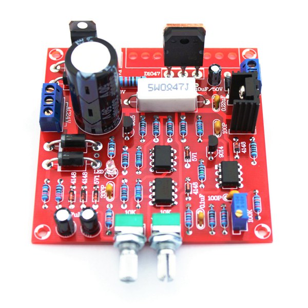
To get straight to the point, the picture below shows the result of this building kit. A PCB of 85 mm by 85 mm on which you solder the complete control electronics for a regulated and stabilised lab power supply. This power supply can, according to the specifications, deliver an output voltage between 0 Vdc and 30 Vdc at an adjustable constant current of up to 3 A.
What you see in this picture consists of two separately ordered products:
- The PCB with the electronics, for sale at AliExpress for less than five euros and at Banggood for € 6.31.
- The heatsink with fan, offered by Banggood for € 4.50.
 |
| This result of an hour's tinkering costs less than eleven euros. (© 2021 Jos Verstraten) |
The building kit of this power supply
Like most Chinese deliveries of small stuff, this kit is delivered sloppily packed in an air cushion envelope. The result was that in our example, the pins of both potentiometers were completely bent and could only be bent straight again with extreme caution without breaking off at the potentiometer body. You can order this kit from Banggood:
Link to order ➡ Hesai power supply PCB kit
 |
| This is how the kit of the power supply board is delivered. (© 2021 Jos Verstraten) |
The quality of the supplied components
This is excellent, there is little to complain about. The large electrolytic capacitor of 3,300 μF has a voltage of 50 V. The 0.47 Ω current sensor resistor is a sturdy wire-wound version of 5 W.
For the package that we received, the two-pole terminal which provides the output voltage was defective. One of the two contacts was missing. When comparing the contents of the package with the parts list, it appeared that two 22 pF capacitors, which are not used in the circuit, were included. Furthermore, a superfluous resistor of 47 kΩ was delivered and one of 4.7 kΩ was missing.
 |
The components present in the package. (© 2021 Jos Verstraten) |
The quality of the PCB
There is nothing to complain. Of course, the PCB is double-sided and equipped with soldermask and component silkscreen. The pads are so big that soldering this board will not be a problem even for the not so experienced hobbyist.
 |
| The two sides of the PCB. (© Hesai) |
The technical data
According to the manufacturer, this regulated power supply meets the following specifications:
- Input voltage: 24 Vac from iron core transformer
- Input current: 3 A max.
- Output voltage: 0 Vdc ~ 30 Vdc
- Ripple and noise: 0.01 % max.
- Constant current: 2 mA ~ 3.0 A
- LED indication in CC mode
The schematic diagram of the power supply
In the figure below, we have reproduced the schematic released by Hesai. In the original we found one error, the position of R5, but we have corrected it. The schematic does not look very much like the well-known straightforward schematic of a linear stabilised power supply. Some explanation is therefore welcome. The colours indicate the components of the various blocks.
The 24 V transformer voltage is rectified by the four diodes of the VDS1 bridge and smoothed by the large capacitor C1 of 3,300 μF. The resistor R1 discharges this electrolytic quickly when the power supply is switched off.
To be able to control from an output voltage of 0 V, the system needs a negative supply voltage. A simple pump circuit was chosen, consisting of the diodes VD4 and VD5 and the two electrolytic capacitors C6 and C7. The negative voltage across C6 is stabilised at about -5.1 V via R16 and VD3. This voltage is used to supply the two op-amps OP1 and OP2 and is also necessary for the operation of the circuit around transistor VT3.

Through stabiliser VR1, a stabilised voltage of 24 V is generated from the positive supply voltage to power the fan of the heatsink.
The internal reference voltage is generated by the op-amp OP3. This is a very strange and rarely used circuit! The zener diode VD6 of 5.1 V is used because of its low temperature drift. When the device is switched on, the feedback around this op-amp causes the output of this IC to become positive. At some point, the output voltage has risen so much that the zener diode is set in its zener region. At that moment, the circuit around OP3 will settle down and a stable voltage of about 10.2 V will appear across resistor R22. The identical resistors R24 and R25 ensure that the op-amp amplifies the voltage of the zener diode twice. This voltage of about 10.2 V is used as a reference for both the current and voltage potentiometers R21 and R13.
 |
| The complete schematic diagram of the control circuit. (© Hesai) |
The circuit (green) around the op-amp OP1 adjusts and stabilises the output voltage of the power supply. Via the voltage divider R9/R10, a part of the output voltage is applied to the inverting input of the op-amp. The non-inverting input is connected to the voltage on the slider of R13 via the resistors R11 and R12. As always, the op-amp will aim for identical voltages on both inputs. The op-amp will drive the darlington VT2/VT1 through the resistor R3 until this voltage equality on both its inputs is reached.
The purple circuit limits the current to an adjustable maximum value. The resistor R6 is used as a current sensor. The inverting input of the OP2 op-amp is set to the zero volt of the negative output of the power supply via the resistor R17. The non-inverting input is set to a small positive voltage provided by the slider of potentiometer R21. Thus, when the power supply is not delivered current, the non-inverting input of OP2 is at a more positive voltage than the inverting one. The output of the op-amp is maximally positive and the diode VD2 is in the non-conducting state.
Now suppose the power supply is loaded with a increasing current. This current creates a increasing voltage across the sensor resistor R6. As a result, the inverting input of OP2 will have a increasing positive voltage. At some point, the current supplied by the power supply becomes so large that the voltage drop across R6 exceeds the voltage set at the non-inverting input of OP2 via R21. The output of the op-amp becomes negative. The diode VD2 will start conducting, causing the voltage at the non-inverting input of OP1 to decrease significantly.
OP1 will now supply less current to the darlington, reducing the output voltage of the power supply. The feedback system around OP2/OP1 therefore ensures that the voltage drop over the current sensor R6 remains equal to the voltage supplied to the non-inverting input of the OP2 op-amp by the potentiometer R21. In other words, the power supply delivers a constant current.
When the system switches to constant current mode (CC), the base of transistor VT4 is pulled to a negative voltage via resistor R15. This semiconductor starts to conduct and the LED HL1 will light up as an indication of the switching from CV to CC mode.
Finally, transistor VT3 is present as a protection against unwanted voltage spikes on the output when the power supply is switched on or off. When the power supply is activated, the base of this transistor is connected to the negative supply voltage via resistor R5. The transistor does not play a role. If the power supply is switched off, the negative supply will almost immediately disappear. This is because there are only two small electrolytic capacitors of 47 μF in this circuit and they discharge almost immediately. The result is that the base of transistor VT3 is driven positive through resistor R4 and starts conducting. The control of the darlington is connected to ground. VT1 immediately goes to the non-conducting state and the output voltage of the power supply goes to zero without any strange transition phenomena. The large capacitor C1 is now discharged via resistor R1.
The cooling of the power transistor
As already written, no cooling for VT1 is included in the basic package. You can make something for it yourself, but you can also order the special package that is custom-made for this PCB. This package costs only € 4.50 and can be ordered via:
Link to order ➡ cooling set
The set contains an aluminium heatsink measuring 45 mm by 50 mm with a thickness of 18 mm and a small 24 Vdc fan. You can attach the fan to the heatsink with the four screws supplied in a rather strange way. By tightening these four screws, you clamp the screws between the lamella of the profile. This seems a rather clumsy way of mounting, but in practice it works very well. The fan is really stuck on the profile. Make sure that the fan side with the nameplate is against the profile. Then the air is blown between the lamella of the heatsink and this is maximally cooled.
In the middle of the heatsink there is a hole tapped with M3 to mount the transistor VT1.
 |
| The parts for cooling the power transistor. (© Banggood) |
The mains transformer
You must power the PCB with a 24 Vac voltage. The Chinese mail order companies recommend a transformer that can deliver 3 A, but this costs € 40.50:
Link to order ➡ Chinese transformer, 3 A
We consider this to be a lot of money for such a simple power supply, which is why we went in search of an alternative. We found the TMB50/002M/1 from Indel at various European mail order companies. It can deliver a maximum current of 2 A, but costs only € 18.65. Two amps is more than enough for a simple lab power supply and that is why we chose this transformer:
Link to order ➡ TMB50/002M/1 transformer, 2 A
However, also read our comment further in this story about the value of the secondary transformer voltage!
 |
| Two usable mains transformers, on the right the Indel. (© 2021 Jos Verstraten) |
Extra: ten-turn potentiometers
You can get started with the described components and build a cheap adjustable lab power supply. However, there are a number of handy extras we can recommend. The two miniature potentiometers supplied work, of course, but there is no way to accurately set voltage and current. It is better to use ten-turn potentiometers. These are available from Chinese mail order companies very cheaply, at € 2.83 each.
Link to order ➡ ten-turn potentiometer
 |
| Ten-turn potentiometers make the power supply easier to operate. (© Banggood) |
Absolutely necessary extras: voltage and current meters
No power supply is complete without voltage and current meters. Nowadays, everyone uses digital panel meters for this purpose. However, we do not consider this a must for a power supply, as there is no need to know the supplied voltage and current values with great accuracy. Moreover, digital panel meters must be powered, which is usually a problem when they are installed in a device. That is why we recommend the two analogue panel meters type 85C1 below. These 30 V and 3 A meters with an accuracy of ±2.5 % and dimensions of 65 mm by 56 mm cost just about € 4.50 each and are accurate enough to be built into a hobby lab power supply.
Link to order ➡ 85C1 voltmeter
Link to order ➡ 85C1 ammeter
 |
| Two inexpensive analogue meters for your power supply. (© Banggood) |
A simple cost calculation
If we add € 10.00 for buttons, a mains cable, a mains switch, a fuse holder and 4 mm chassis parts, we end up with a total of approximately € 55.00 for this power supply. Of course, you will have to build the housing yourself!
Building the Hesai power supply
The assembly instructions
As usual for a Chinese product, this package is supplied without a construction manual. You can, of course, solder this kit together without any documentation, based on the component labels on the PCB. However, we have found a site on the Internet from which you can download a very detailed construction description (33 pages!) for this power supply.
Download link ➡ the construction manual
We have nothing to contribute except for this photo which clearly shows how to mount the fan on the heatsink and how to screw it onto the board afterwards.
 |
| Mounting the cooling fan and the heatsink on the PCB. (© 2021 Jos Verstraten) |
X-ray view of the PCB
What might also be useful as an extra service to the hobby-builder is this 'x-ray view' of the PCB, where in one illustration you can see both the red tracks on the component side and the blue tracks on the solder side. Ideal if you need to find a fault in your construction!
 |
| Combination of both track patterns in one illustration. (© Hesai) |
The Hesai 30 V power supply in practice
Switching on the power supply
The first thing you notice is that the power supply sometimes starts up in CC mode and provides an output voltage of 0 V. The LED lights up and the circuit does not work. Fortunately, it helps to switch off the mains voltage and then switch it on again. This strange action is probably due to the unusual circuitry used to generate the internal reference voltage.
Adjusting the R7 potentiometer
With this adjustment potentiometer you must compensate the offset of the operational amplifier OP1. Turn the potentiometer with which you set the output voltage (R13) to the lowest position. Now turn the trimmer R7 until the power supply provides an output voltage of 0.0 V.
An important note about the supply voltages
With the 24 V transformer we used, the following two supply voltages were measured in no-load condition:
- positive voltage: +34.48 V
- negative voltage: -5.25 V
Two of the three op-amps are powered between these two voltages. That means there is a total voltage of 39.73 V between the power supply pins of these ICs! However, the data sheet of the TL081CP shows that the absolute maximum supply voltage of this op-amp should be only 36.0 V. It is of course difficult to investigate what this overvoltage means for the long-term health of the circuit. In any case, the way the designers handle these op-amps doesn't deserve a beauty prize!
We therefore advise every rebuilder not to use a 24 V transformer, but a 20 V type. In practice, this means that you cannot set the output voltage to 30 V, but only to about 24 V. For most applications, this is good enough and at least it gives you the certainty that the op-amps will not fail at an unpredictable moment.
The switching on and off behaviour of the power supply
As described, a circuit has been built into the power supply to ensure that no voltage spikes occur at the output when the power supply is switched on or off. To investigate this, we set the power supply to a voltage of 12 V, a current of 1 A and connected it to a resistor of 22 Ω. We then switched the power supply on and off and observed the output voltage on our oscilloscope. In the picture below, we have combined both observations into one photo. This clearly shows that the power supply does indeed behave nicely. Note the difference in time base speed when switching on and off! What is striking is that the voltage rises very quickly, much faster than the large reservoir-elco C1 can charge. The circuit around transistor VT3 apparently switches the output voltage only on at the moment the reservoir-elco is charged.
 |
Switch-on and switch-off behaviour of the power supply with a 0.5 A load. (© 2021 Jos Verstraten) |
Measuring the output stability and ripple at 5.0 V output voltage
In the table below, we have summarised the behaviour of the power supply at an output voltage of 5.0 V and an increasing load up to 2.0 A. We measured the ripple with our Philips PM2454 analogue millivolt meter. To put the results in perspective: between no-load and full-load, the output voltage drops by only 47 mV. That is equivalent to an internal resistance of 0.023 Ω.
 |
| Output stability and ripple/noise at 5.0 V output voltage. (© 2021 Jos Verstraten) |
Of course, we also looked at the ripple and noise on the screen of the oscilloscope under a load of 2 A. At the most sensitive setting of 1 mV/div, a very small 100 Hz hum is visible and about five mV of noise.
 |
| The ripple and noise at 5.0 V and 2.0 A on the oscilloscope. (© 2021 Jos Verstraten) |
Measuring the output stability and ripple at 12.0 V output voltage
We repeated the same measurements at an output voltage of 12.0 V. Also at these parameters, the power supply behaves very well. Up to 1.0 A load current, the output voltage remains constant to the millivolt. The total voltage drop of 21 mV corresponds to an internal resistance of only 0.01 Ω. It makes no sense to publish an oscillogram, because this is equal to that at an output voltage of 5.0 V.
 |
| Output stability and ripple/noise at 12.0 V output voltage. (© 2021 Jos Verstraten) |
Measuring the output stability and ripple at 24.0 V output voltage
It is clearly noticeable here that the power supply is no longer able to maintain the stability of the output voltage at currents in excess of 1 A. A closer examination shows that the transformer is to blame. The unstabilised DC voltage across C3 drops from 33.83 V at no load to 26.79 V at full load, leaving too little voltage for the control system on the PCB.
As the oscillogram below shows, the value of 1.15 V ripple at 2.0 A load is not so surprising. You can see the 100 Hz ripple, originating from the bridge rectifier, present on the output voltage.
Measuring the output stability and ripple at 30.0 V output voltage
As can be expected, the results at 30.0 V are even worse. The power supply cannot deliver more than 0.5 A at such an output voltage.
Voltage stability and thermal behaviour under load of 2.0 A
We have set the output voltage to 5.00 V and loaded the power supply with a current sink of 2.0 A. We were very curious to find out whether the cooling capacity of this rather small heatsink is sufficient to prevent overheating of the power transistor. To our surprise, this is indeed the case, see the table below. After fifteen minutes, the temperature of the heatsink had stabilised at around 62 °C. Apparently, the influence of such a small fan makes a lot of difference to the removal of the heat produced.
The long-term stability of the output voltage is, for a hobby product, excellent. During this heating cycle of the PCB, the output voltage only decreases by 47 mV or 0.94 %.
Current stability and thermal behaviour when set to 2.0 A
A final important feature that deserves to be tested is the stability of the power supply in CC mode. We first set the PCB at no-load to 12.0 V, short-circuited the power supply with our current measurement multimeter and set the output current to 2.0 A. We then monitored the trend of this current and the temperature of the heatsink. The results are summarised in the table below and are again excellent. The current changes by only 23 mA or 1.1 %.
Hum and noise in CC mode
The ability to limit the maximum current via the CC mode is primarily intended as a safety feature in your experiments. In daily lab practice it will not often happen that you actually use the power supply as a constant current source. For the sake of completeness of this test, we have nevertheless measured what the output voltage looks like when you work in CC mode. We have set the power supply without load to 16 V, connected a resistor of 8 Ω to it and set the current to be supplied to 1.0 A. The power supply works in CC mode and via the oscilloscope you can discover how the voltage looks like. Well, that is disappointing! With the millivolt meter we measure an AC voltage of no less than 48 mV on the output. The picture below appears on the screen of the oscilloscope. So there is a very large, strangely shaped ripple on the output voltage in CC mode. If the current potentiometer is turned on until the LED goes out and the power supply is back in CV mode, this large ripple will disappear like snow in the sun.
It is clearly noticeable here that the power supply is no longer able to maintain the stability of the output voltage at currents in excess of 1 A. A closer examination shows that the transformer is to blame. The unstabilised DC voltage across C3 drops from 33.83 V at no load to 26.79 V at full load, leaving too little voltage for the control system on the PCB.
 |
| Output stability and ripple/noise at 24.0 V output voltage. (© 2021 Jos Verstraten) |
As the oscillogram below shows, the value of 1.15 V ripple at 2.0 A load is not so surprising. You can see the 100 Hz ripple, originating from the bridge rectifier, present on the output voltage.
 |
| The ripple at 24.0 V and 2 A on the screen of the oscilloscope. (© 2021 Jos Verstraten) |
Measuring the output stability and ripple at 30.0 V output voltage
As can be expected, the results at 30.0 V are even worse. The power supply cannot deliver more than 0.5 A at such an output voltage.
Voltage stability and thermal behaviour under load of 2.0 A
We have set the output voltage to 5.00 V and loaded the power supply with a current sink of 2.0 A. We were very curious to find out whether the cooling capacity of this rather small heatsink is sufficient to prevent overheating of the power transistor. To our surprise, this is indeed the case, see the table below. After fifteen minutes, the temperature of the heatsink had stabilised at around 62 °C. Apparently, the influence of such a small fan makes a lot of difference to the removal of the heat produced.
The long-term stability of the output voltage is, for a hobby product, excellent. During this heating cycle of the PCB, the output voltage only decreases by 47 mV or 0.94 %.
 |
Voltage stability and thermal behaviour at 5.0 V and 2.0 A. |
Current stability and thermal behaviour when set to 2.0 A
A final important feature that deserves to be tested is the stability of the power supply in CC mode. We first set the PCB at no-load to 12.0 V, short-circuited the power supply with our current measurement multimeter and set the output current to 2.0 A. We then monitored the trend of this current and the temperature of the heatsink. The results are summarised in the table below and are again excellent. The current changes by only 23 mA or 1.1 %.
 |
| Constant current mode and thermal behaviour. (© 2021 Jos Verstraten) |
Hum and noise in CC mode
The ability to limit the maximum current via the CC mode is primarily intended as a safety feature in your experiments. In daily lab practice it will not often happen that you actually use the power supply as a constant current source. For the sake of completeness of this test, we have nevertheless measured what the output voltage looks like when you work in CC mode. We have set the power supply without load to 16 V, connected a resistor of 8 Ω to it and set the current to be supplied to 1.0 A. The power supply works in CC mode and via the oscilloscope you can discover how the voltage looks like. Well, that is disappointing! With the millivolt meter we measure an AC voltage of no less than 48 mV on the output. The picture below appears on the screen of the oscilloscope. So there is a very large, strangely shaped ripple on the output voltage in CC mode. If the current potentiometer is turned on until the LED goes out and the power supply is back in CV mode, this large ripple will disappear like snow in the sun.
 |
| The big ripple on the output voltage in CC mode. (© 2021 Jos Verstraten) |
Our conclusion about the Hesai 30 V ~ 3 A power supply
The fact that the designers of this power supply specify a transformer voltage of 24 V is a very serious violation of the maximum specifications of the parts used. We have already given our opinion on this in the story. We therefore strongly recommend the use of a 20 V / 2 A transformer!
The maximum output voltage of 24 V and the maximum current capacity of 2 A are large enough for almost all hobby applications. Within this limitation, this power supply will be very useful for all your experiments working in CV mode. For those rare applications where you need a constant current you have to consider the large ripple created on the output voltage in CC mode.
Admittedly, you can buy a ready-to-use Chinese switched power supply for an almost comparable price. The real hobbyist naturally wants to build himself and this control print is an excellent basis for designing a good usable lab power supply for your hobby lab.

30V 3A Power Supply DIY Kit