
|
For about € 25.00 you buy the control electronics for a self-constructed linear, but digitally adjustable, power supply. However, you do need to buy a few extras. |
Introduction to the Hiland 28 V ~ 2 A power supply kit
The end result
To get straight to the point, we show you the end result of this kit. Two small PCBs on which you find the complete control electronics for a linear power supply with an output voltage of 0.1 V to 28.0 V and a current limit of 0.01 A to 2.00 A. The control system of the power supply works, in the traditional old-fashioned way, completely analog (linear). So between the unstabilized input voltage and the stabilized output voltage is a serial transistor. That electronics is on the largest PCB.
However, you set both the current and voltage digitally with two rotatable and clickable encoders. The set values appear on a display with, of course, the currently supplied voltage and current as well. That digital part of the circuit is housed on the small PCB. You need to connect both PCBs together using a five-wire cable.
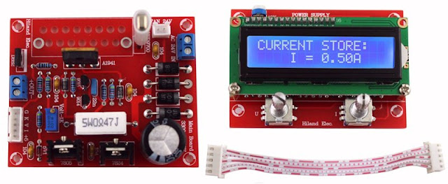 |
The end result of this kit. (© 2024 Jos Verstraten) |
Manufacturer, model, suppliers and price
This kit is made by Hiland but is also offered under the name Aneng. Who designed the circuit is not clear. The kit also has no type number, but if you search for 'Hiland 28V 2A supply' or 'Aneng 28V 2A supply' via Google, you will find plenty of suppliers selling the kit via AliExpress or Amazon. Prices vary quite a bit, but the cheapest supplier offers the kit through AliExpress for € 16.92 plus € 5.64 for shipping.
Delivery of the kit
As usual, the parts are squeezed together in a far too small plastic bag. Fortunately, the one IC, an ATMEGA8, and its socket are attached to a piece of foam so that the pins of both parts survive the sloppy packaging in good condition.
Unfortunately, no building instructions are included, but thanks to this comprehensive article, building this kit from scratch will be no problem.
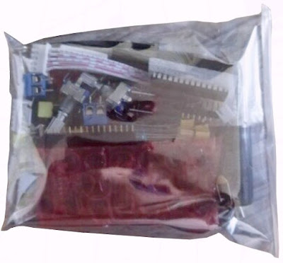 |
| The delivery of the components. (© 2024 Jos Verstraten) |
The supplied components
In the picture below you can see what all you get for the mere sum of about twenty-five euros. The display is the well-known LCD1602, an off-the-shelf module that can put two lines of text of sixteen characters each on an LCD. To connect the secondary voltage of the transformer and the stabilized output voltage, two PCB screw terminal blocks are used. Below the LCD1602, you will notice a rather odd-looking component. That is a thermo switch KSD9700. This switches on at a temperature of 50 °C. The intent of the designers is that you mount this part in good thermal contact with the heatsink and use it to turn a fan on and off.
 |
| The supplied parts. (© 2024 Jos Verstraten) |
Power supply specifications
According to the data on the product pages, this power supply has the following characteristics:
- Input voltage: 24 Vac ~ 30 Vac, 2 A
- Output voltage: 0.1 Vdc ~ 28.0 Vdc
- Resolution voltage setting: 100 mV
- Limiting current: 0.01 A ~ 2.00 A
- Resolution current setting: 10 mA
- Modes: constant voltage or constant current
- Memory: one voltage value and one current value
- Dimensions main board: 85 mm x 67 mm
- Dimensions display board: 80 mm x 55 mm
So strangely, nothing at all is specified about the surely important specs of each power supply, namely the ripple on the output voltage, the accuracy of the settings and the degree of stabilization. We shall see at the tests!
What you need to purchase extra
The transformer
In most advertisements, a transformer with a secondary voltage of 24 V is recommended. However, the power supply is adjustable up to 28 V, and for that we think a 24 V transformer is a bit on the tight side. According to the specs, however, you can supply up to 30 Vac voltage to the PCB. So we purchased the transformer below, which costs € 37.78 and can supply 30 V at 2 A. You can easily find this part by googling 'Ei66 30V'. Important information: the red wires make up the 230V primary winding.
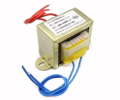 |
| The 30 V transformer we used. (© AliExpress) |
The heatsink and fan
Space is reserved on the PCB for an heatsink. However, the available width is only 45 mm and it takes quite a bit of effort to find a heatsink that fits into this limited space. We found the profile below at AliExpress (search for 'Heatsink 40mm x 40mm x 100mm') that costs only € 9.33.
Fans that are 40 mm by 40 mm in size can be easily found at AliExpress. We bought model EB40101S2-000U-999 from the Sunon brand which is powered from 12 Vdc. With two of these fans costing only € 2.45 you can keep the heatsink nice and cool even at maximum load on the power supply. You can connect these fans in series, because a 24 Vdc connection for the fan is standard on the power supply board.
 |
| The heatsink and fans we used. (© 2024 Jos Verstraten) |
Construction of the controller board
The schematic
The figure below shows the schematic of this part of the power supply. At the top, you can see five contacts that are connected to the other PCB through the flat ribbon cable:
- G: ground.
- K: driving the control transistor(s) in the analog board.
- V: measurement of the output voltage.
- I: measurement of the output current.
- +5 V: power supply for the digital part.
Unfortunately, the kit lacks a good manual that also explains how the circuit works.
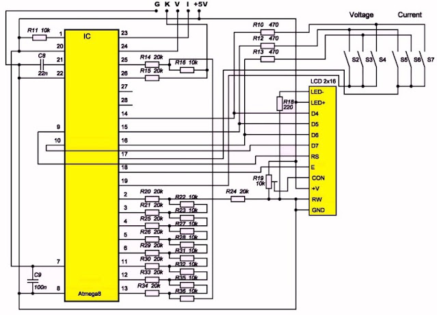 |
| The schematic of the digital part of the power supply. (© 2024 Jos Verstraten) |
The PCB of the controller
The two sides of this PCB are represented in the figure below.
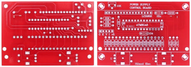 |
| The controller PCB. (© 2024 Jos Verstraten) |
Assembling the controller PCB
You start by soldering the 25 resistors. After that comes the one capacitor of 100 nF. Next, solder the IC socket. Solder the black 16-pin connector onto the PCB, the 22 nF capacitor and the 10 kΩ adjustment potentiometer.
Turn the PCB over and mount the five-pole connector for the ribbon cable in the correct position on the solder side of the PCB. Turn the PCB over again and solder the five pins of this connector to the component side of the PCB. The correct position of this connector follows from the picture below.
 |
| The assembly of the five-pole connector. (© 2024 Jos Verstraten) |
Solder the two rotary encoders and finally mount the two 10 mm copper spacers on the component side of the PCB. Mount the IC in the socket.
You can see the result of all these activities in the picture below.
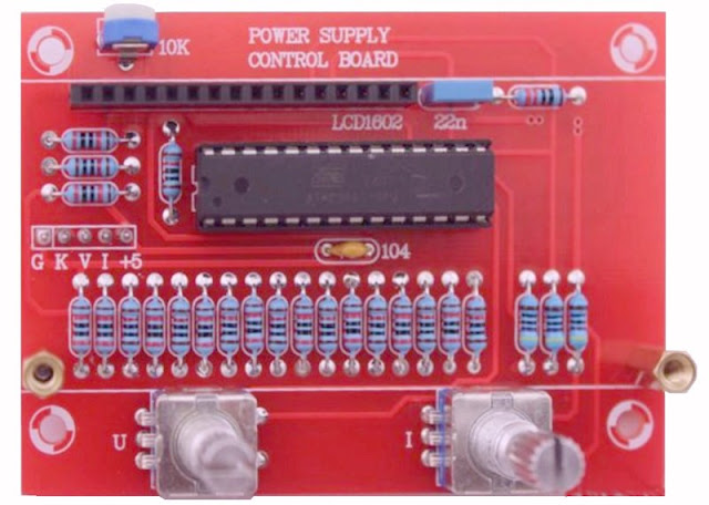 |
| The completely soldered controller PCB. (© 2024 Jos Verstraten) |
Next, mount the 16-pin PCB header with the short pins on the component side of the LCD1602 PCB. Plug this PCB into the black connector on the controller PCB and secure the LCD1602 PCB with two bolts in the two 10 mm spacers. This part of the power supply is now ready and should look as shown in the picture below.
 |
| The combination of controller and display board. (© 2024 Jos Verstraten) |
The construction of the analog PCB
The schematic of the analog part
This is drawn in the figure below. An A1941 is used as the serial transistor VT1. This is an equivalent of the Japanese 2SA1941 silicon PNP power transistor. It can handle 10 A of collector current at a maximum power of 70 W. The maximum collector/emitter voltage is 140 V. Obviously, an output of the microcontroller cannot supply enough current to directly drive the base of this semiconductor. Hence the three transistors VT2, VT3 and VT4 that form a current amplifier to provide sufficient base current to VT1. This circuit is driven from the output K of the controller PCB.
The resistors R3, R5 and R7 are the voltage divider that feedbacks some of the output voltage through the wire V to the microcontroller. By adjusting R7, you can ensure that the output voltage of the power supply becomes equal to the value that appears on the display.
R8 is the current sensor resistor that provides the feedback of the current through the wire I of the flat ribbon cable.
The analog board contains two voltage stabilizers VR1 and VR2 that provide +5 V and +24 V for the microcontroller and the fan, respectively.
The switch S1 is the schematic representation of the thermoswitch KSD9700. It closes at the moment when the heatsink of the transistor VT1 becomes hotter than 50 °C.
It may be noted that only a small capacitor of 100 nF is switched across the output terminals of the power supply and not a large electrolytic. This is not allowed in a power supply with adjustable current limiting, because the charge in such a large electrolytic can cause the power supply to deliver a much higher current than you have set.
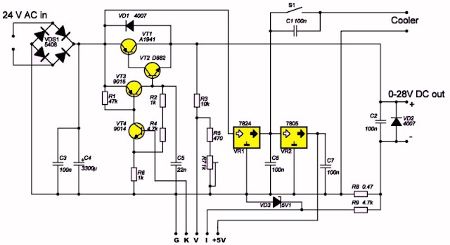 |
| The schematic of the analog part of the power supply. (© 2024 Jos Verstraten) |
The PCB of the analog part
In the picture below you can see both sides of the analog PCB of this power supply.
 |
| The two sides of the analog PCB. (© 2024 Jos Verstraten) |
Assembling the analog PCB
Start by soldering the small 5V1 zener diode next to where the 7805 should go. Pay attention to polarity! Then continue soldering the seven resistors. Next step is to solder the five 100 nF capacitors. Solder the two 1N4007 diodes, again paying close attention to the location of anode and cathode. Soldering the one 22 nF capacitor concludes the assembly of the smaller components.
Push the two transistors 9015 and 9014 into the PCB and solder them in place. Prepare the rectifier for operation by mounting and soldering the four 1N5408 diodes on the PCB. Make sure these components float a few millimetres above the surface of the PCB.
Now it is time for the five-pole connector for the ribbon cable, pay attention to its position! Solder the two PCB screw terminal blocks, obviously with the holes facing outwards. You can now mount and solder the adjustment potentiometer R7 (Volt-1K is printed on the PCB) in place. Note the position of the adjustment screw!
Next, you can press and solder the transistor D882 into the PCB. Again, note the position, the metal back is facing inwards. Mount the 0.47 Ω wire-wound resistor on the PCB in such a way that there is half a centimetre of space between the PCB surface and the underside of this resistor.
Screw the two voltage stabilisers VR1 and VR2 onto the heatsinks and mount them on the PCB. Mount the large smoothing capacitor in the lower right corner of the PCB and solder it in place. Pay attention to the plus and minus!
In the top right corner are now open places for the thermoswitch and the super-small connector intended for connecting a 24 V fan. We did not use this thermoswitch because the fans we bought hardly make any noise, so they might as well continuously cool the A1941's heatsink. We connected these fans to the PCB with wires, so the small connector was also unnecessary for us.
 |
| The assembled analog PCB. (© AliExpress) |
Mounting the A1941 serial transistor
In the picture above, this transistor is already soldered into the PCB. This is only applicable if you use a heatsink that fits on the PCB and is also premature. However, you can also mount the power transistor on a separate heatsink and connect the three terminals to the PCB with the shortest possible wires.
CAUTION! If you screw the transistor onto a heatsink, this heatsink is connected to the collector of the transistor and thus, see the schematic, to the output voltage of the power supply. So always mount this transistor isolated on a loose heatsink!
If you follow our assembly, you must first determine where a hole should be made in the heatsink for mounting the A1941. Mount this transistor as high as possible on the heatsink, so that the three leads can just be soldered into the three holes on the PCB. Next, mount the fans on the back of the profile. This is best done with self-tapping screws, which you screw into small holes drilled in the two flanges of the heatsink. Fit a couple of metal washers to allow the fans to rotate freely and mount these parts so that the air is blown into the heatsink. You must of course wire the two 12 V fans is series, paying attention to the plus and minus.
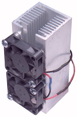 |
Mounting the fans on the heatsink. (© 2024 Jos Verstraten) |
The final assembly of the analog PCB
You can then screw the heatsink with transistor onto the PCB with self-tapping screws. If you use the heatsink we recommend, you can tighten the screws between two ribs of the heatsink. There are two holes in the PCB that do fit! When doing this, take note that the PCB track leading to the emitter of the transistor is located quite close to these holes. If necessary, use plastic washers under the screws so that no short circuit can occur with this PCB track. Finally, solder the three leads of the transistor and the two wires of the fans into the PCB. Again, pay attention to polarity.
 |
| The fully assembled analog PCB. (© 2024 Jos Verstraten) |
Working with the Hiland power supply
The final assembly
Connect the two PCBs with the flat ribbon cable provided. Screw the two blue secondary wires of the power supply transformer into the corresponding PCB's screw terminal block. Solder two 4 mm banana chassis sockets to two wires and screw this wires in the output screw terminal block. This way, you can easily connect your measuring equipment, such as a multimeter and an oscilloscope, to the output of the power supply.
The first test
Connect the primary of the transformer to the 230 V mains. You will notice that the output voltage of the power supply becomes equal to about 5.0 V and that the display lights up evenly without showing any text, however. Turn the adjustment potentiometer R19 on the controller PCB until the characters appear clearly legible on the display.
Turn the adjustment potentiometer R7 on the analogue board until the output voltage of the power supply becomes equal to the value shown on the display.
This power supply is very easy to operate. With the left rotary encoder, you set the value of the output voltage with a resolution of 0.1 V. With the right encoder, you define the maximum current the power supply can deliver with a resolution of 10 mA. By pressing the encoder, the set value is stored in memory and becomes the value at which the power supply starts up again next time. The figure below shows the various messages that may appear on the display:
- A:
Start-up screen that appears approximately one second after switching on the mains power. - B:
The normal display while working with the power supply. On the top line 'SET' you will see the memorized start-up values of voltage and current. The current values of output voltage and current appear on the bottom line. - C:
Appears on the display when you press either encoder. The set value is stored in memory and becomes the new 'SET' value. - D:
'<OL>' will appear on the left of the bottom line if the power supply would like to supply more current than the 'SET' value allows. The value of the output voltage is then reduced to the value at which the power supply will supply the set SET current.
 |
| The messages on the display. (© 2024 Jos Verstraten) |
Testing the Hiland power supply
Accuracy of the output voltage
The table below shows in the left column the set value of the output voltage and in the right column the actual output voltage, measured with our Fluke 8842A multimeter. These measurements were taken at no load, i.e. with open output terminals. You will no doubt agree with us that these are excellent results!
 |
Output voltage accuracy. (© 2024 Jos Verstraten) |
Accuracy of the output current
We short-circuited the power supply with our multimeter ET3255, set to measure DC currents, and measured the short-circuit current at various set values of the limiting current. The results are summarised in a table. Again, we can only conclude that the power supply performs excellently.
 |
| Output current accuracy. (© 2024 Jos Verstraten) |
Output stability and ripple at 5.0 V
The table below shows how constant the output voltage remains when set to 5.0 V and at various output currents. Of course, we have set the current limitation to the maximum value of 2.00 A. In the right-hand column, the rms value of the ripple at the 5.0 V output is measured with our Philips AC voltage millivoltmeter PM2454B. Curiously, the ripple first increases with increasing load current, but then decreases again.
An rms value of 20 mV on an output voltage of 5.0 V corresponds to 0.4 % ripple, which is in fact quite a lot for a modern power supply. But for hobby use, which is what this power supply is typically designed for, this is an acceptable value.
If the power supply is loaded with a current of 1.9 A, the output voltage drops by 0.1056 V. From this, you can calculate that the internal resistance of the power supply equals 0.056 Ω. This is an excellent value!
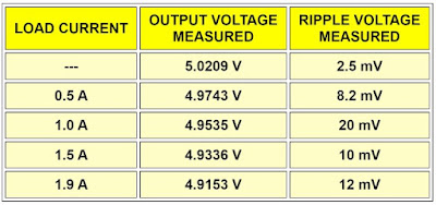 |
| Output stability and ripple at 5.0 V. (© 2024 Jos Verstraten) |
Output stability and ripple at 12.0 V
We repeated this test at an output voltage of 12.0 V. You can see the results in the table below. Here, the voltage drops by 0.1059 V between 0 A and 1.9 A. The internal resistance of the power supply remains the same.
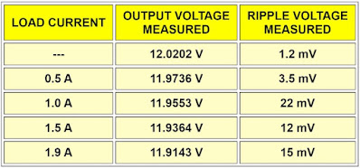 |
| Output stability and ripple at 12.0 V. (© 2024 Jos Verstraten) |
Output stability and ripple at 24.0 V
Finally, another measurement is made at an output voltage of 24.0 V. Now the voltage drop over the entire current range is 0.133 V. This corresponds to an internal resistance of 0.07 Ω.
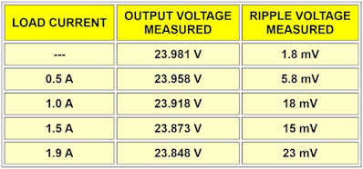 |
| Output stability and ripple at 24.0 V. (© 2024 Jos Verstraten) |
The ripple on the oscilloscope
Of course, during these measurements, we not only measured the output voltage with our Fluke 8842A, but also observed it on our oscilloscope. You can see in the oscillogram below the ripple at 5.0 V output voltage and a current of 1.9 A. In the other measurements, the shape of the ripple did not differ much from this picture. The period of the ripple is 10 ms, which thus corresponds nicely to the 100 Hz provided by the bridge rectifier.
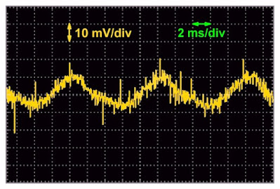 |
| The ripple at 5.0 V and 1.9 A. (© 2024 Jos Verstraten) |
Switching the power supply on and off
When you switch a power supply on or off, no voltage spikes or oscillations should appear on the output. In the picture below, you can see what happens if you first switch the power supply set to 12.0 V and loaded with 1.0 A on and then switch it off again a few seconds later. The voltage rises nicely and drops just as nicely again.
 |
| Switching the power supply on and off. (© 2024 Jos Verstraten) |
Behaviour when connecting and disconnecting a load
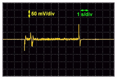
In the oscillogram below, you can see the behaviour of the power supply set to 12.0 V when a load that draws 1 A from the power supply is first connected and then removed. As can be expected, switch-on and switch-off transients do now occur on the output voltage. After all, the control system that has to keep the output voltage constant does not operate without delay. Hence, you can see that the output voltage drops by 75 mV for a short time when the load is connected. However, the control system ensures that this voltage drop is quickly compensated. When the load is removed, the output voltage goes up by 110 mV, but even that increase is compensated fairly quickly by the control system.
 |
| Behaviour when a load is switched on and off. (© 2024 Jos Verstraten) |
Heating up the heatsink
In any linear power supply, a lot of power is consumed in the serial transistor. After all, it has to absorb the difference between the unstabilised voltage and the output voltage. We set the power supply to a current at 2.00 A. Afterwards, we mounted a thermocouple between two ribs of the heatsink and measured the temperature. The power supply is short-circuited so that the output voltage becomes zero and the serial transistor has to handle the maximum unstabilised voltage. After 15 minutes, the temperature of the heatsink had risen to +45.4°C, and after half an hour to +46.2°C. Clearly, even after installing the PCBs in an enclosure, you need not fear too hot semiconductors. The transformer gets much hotter than the heatsink!
Built into an enclosure
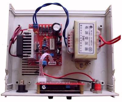
This is something we are happy to leave to your imagination! If you followed our instructions with the ten centimeters high heatsink, you can opt for a narrow, tall enclosure. On the internet you will find hobbyists working with a 24 V transformer and using a much smaller heatsink. In the picture below, borrowed from the internet, you can see how you can then fit the electronics in a flatter enclosure. In this picture, the power switch, on the left of the front panel, is not yet connected. Don't forget to include a fuse in the 230 V wiring!
 |
This way, you can build the electronics into a cabinet. (© Bricolages-electroniques) |

Buy this power supply at Amazon


