|
On the PCB is stated 'transistor tester', but that does this kit of about € 15.00 great injustice. With the M8 you can test almost all your components: resistors, potentiometers, capacitors, coils, diodes, LEDs, thyristors, triacs, transistors, FETs and MOSFETs. It can also be used to generate and measure frequencies. |
Introduction to the M8 kit
Good parts, missing manual
Chinese suppliers are not exactly known for their excellent product descriptions. The supplier of this kit is a good example of this. Excellent parts, a PCB of great quality but no manual is included! Although you can download an 'Installation Instruction' via the internet, you cannot find a good step-by-step construction description.
 |
| An overview of all components. (© 2018 Jos Verstraten) |
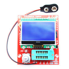
The figure below shows how the M8 (also called M12864 by various mail order companies) will look like. The device is mounted on a 65 mm by 75 mm PCB and is powered by a 9 V battery (not included). A LCD display of 128 x 64 pixels dominates the PCB. The electronic components are hidden under that display, including the ATMEGA328 microcontroller that controls the circuit. This microcontroller is very well known thanks to the Arduino. Below the display is a rotary encoder on the left and on the right a 14-pin ZIF IC-socket to connect the components to be tested. ZIF stands for 'Zero Insertion Force', thanks to the lever you can insert the connecting wires of the tested components into the contacts without applying force. Afterwards, close the contacts by pushing the lever downwards. The 14 pins are connected with the three input ports TP1, TP2 and TP3 that you will see on the display with every measurement. There are only four contacts in the socket for TP2! In the upper right corner of the PCB there are two contacts for measuring the frequency of a signal. At the bottom right are three tin-plated test pads for measuring SMD components. In addition, there are three more contacts connected to the three ports. If you use the M8 to generate rectangular signals, these are available between ports TP2 and TP3. A specific ground connection cannot be found.
 |
| The parts of the assembled component tester. (© 2018 Jos Verstraten) |
- Resistors.
- Potentiometers.
- Capacitors.
- Electrolytic capacitors.
- Coils.
- Diodes.
- LEDs.
- Bipolar transistors, NPN and PNP.
- Darlingtons, NPN and PNP.
- FETs, N and P channels.
- IGBTs, N and P channels.
- MOSFETs, N and P channels.
- Thyristors (with restrictions).
- Triacs (with restrictions).
- Frequencies.
For all these measurements, not only the value of the relevant parameters appears on the display, but also the component symbol and connection data.
What signals can the M8 deliver?
In the 'f-Generator' menu selection, the device provides rectangular output signals with an amplitude of 5.0 V and frequencies between 1 Hz and 2 MHz, although with bandwidth limitations.
In the '10-bit PWM' option, the generator delivers a pulse with an amplitude of 5.0 V and a frequency of 7.812 kHz, with a adjustable duty cycle between 1 % and 99 %.
The circuit diagram of the component tester
The figure below shows the complete circuit diagram of the device.
 |
| The complete circuit diagram of the component tester. (© Hiland) |
- Display type: LCD 12864
- Dimensions of the display: 50 mm x 35 mm
- Supply voltage: 5 Vdc to 12 Vdc
- Standby current: less than 20 nA
- Current in operation: 24 mA typical for 9 Vdc power supply
- Resistance measurement: 50 MΩ max.
- Capacity measurement: 25 pF to 100 mF
- Induction measurement: 0.01 mH to 20 H
- Resolution of component measurements: four digits
- Frequency measurement: 1 Hz to 25 kHz at 5.0 V max.
- PCB dimensions: 75 mm x 65 mm
The construction of the component tester
Assembling the PCB
All delivered parts are 'old-fashioned' parts with connecting wires, not SMD. Soldering the PCB is a job that is done in half an hour. Mount and solder the parts in this order:
- The 22 resistors.
- The two ceramic capacitors of 22 pF (coding 22).
- The capacitor of 10 nF (coding 103).
- The five capacitors of 100 nF (coding 104).
- The crystal of 8 MHz.
- The IC socket for the microcontroller, do not mount this part in the socket yet.
- The eight-pole connector for the display.
- The LED, the long connection wire is the anode (+).
- The two NPN transistors (coding 9014).
- The one PNP transistor (coding 9012).
- The 5 V stabilizer (coding 7550).
- The 2.5 V reference diode (coding TL431).
- The two electrolytics of 10 µF, note the plus and minus.
- The yellow reference capacitor C1 (coding 1nJ).
- The ZIF socket with the lever to the edge of the PCB.
- The rotary encoder.
 |
| The PCB before mounting the microcontroller and the display. (© 2018 Jos Verstraten) |
The 9 Vdc supply voltage of the battery must be reduced to 5 Vdc for the microcontroller and the display. You have already soldered the stabilizer to the PCB, but now you need to check whether this voltage reduction works. Solder the battery clip on the PCB with the red wire in the plus and mount the battery in the clip. Now put a multimeter between pins 7 and 22 of the IC socket. Close the switch in the rotary encoder by pressing the axis of this part. You should now measure a voltage of 5.0 V.
Installing the microcontroller and the display
Remove the battery from the clip and carefully install the microcontroller into the IC socket. Make sure that none of the pin bends inwards. Above the LED and the ZIF socket you will see two 3 mm holes. Install the two metal spacers here by attaching them to the PCB with the supplied bolts. These spacers serve as support for the display. Then solder the eight-pole header into the holes 5 to 12 of the display, as shown in the figure below. Now install the display with this header in the PCB connector and secure the display with the two remaining bolts. Reconnect the 9 V battery to the circuit.
 |
| The position of the eight-pole header on the display PCB. (© Hiland) |
For approximately € 6.00 extra you can buy the 'Original Hiland Supporting Shell'. This is a plastic enclosure in which you can mount the PCB of the Hiland M8. However, you first have to remove the 14-pin ZIF socket from the PCB, which is not very easy. The function of this socket is taken over by a five-pole connector that you install on the front panel and that you connect to the PCB. Under this connector two 4 mm connectors are mounted, which are connected to connections 1 and 3. A battery compartment is provided in the back of the housing. This means you can convert the M8 PCB into a very inexpensive, easy-to-handle component tester.
 |
| The parts of the enclosure that you can buy extra. On the right you can see the end result of the mounting of the PCB in the enclosure. (© 2018 Jos Verstraten) |
Calibrating the component tester
The tester has a fairly extensive self-test and calibration procedure. Connect two wire bridges between TP1 and TP2 and between TP2 and TP3. Now briefly press the shaft of the encoder. The microcontroller measures the voltage of the battery and the 5.0 V voltage and then puts the text 'Selftest mode' on the display. Some screens with data will follow, at some point you will see the text 'Isolate probe'. Remove the two wire bridges from the socket. The calibration procedure continues. After a while the symbol of a capacitor will appear with the text '>100 nF' next to it. You must now connect the remaining red capacitor with the imprint 224 (220 nF) between TP1 and TP3. A little later the text 'Test end' appears on the display and you can remove the capacitor again. The component tester is now ready for use.
Working with the M8 component tester
Remarks
The circuit is extremely sensitive to voltages on the three ports TP1, TP2 and TP3. Make sure that capacitors, especially electrolytics, are fully discharged before connecting these parts to the tester.
No matter to which of the three ports you connect a component, the tester is so smart that it can find out how you connected the component. Of course, for tripods, you must use the three ports. However, passive components can be connected arbitrarily between two of the three ports.

Extremely simple operation
Working with the component tester is extremely simple. Connect the part to be tested between two of the three TP's (or between all three, of course) and press the encoder. The tester first shows the battery voltage and the value of the 5.0 V supply voltage for the processor and a little later the result of the measurement appears on the screen. Press the encoder for two seconds and the selection menu appears, see figure below. Turn the encoder until the 'Switch off' option is selected and press the encoder. The unit returns to standby mode. If you do not press the encoder, the unit will automatically enter standby mode after approximately 28 seconds.
If you want to test several components in succession, you can remove the measured component, connect the new one and press the encoder briefly. The device then immediately starts a new measuring cycle.
 |
| The selection menu that appears when you press the encoder for more than two seconds. (© Hiland) |
If you press the encoder for more than two seconds, the menu appears on the screen. By turning the encoder you can enable any of the following functions, confirm your selection by pressing the encoder:
- Switch off:
The device switches off. - Transistor:
Measuring components. - Frequency:
Measuring frequencies. - f-Generator:
Generation of a rectangular voltage with adjustable frequency. - 10-bit PWM:
Generation of a rectangular voltage with adjustable duty cycle. - C+ESR@TP1-3:
A special measuring mode in which you can test capacitors between 2 µF and 50 µF in-circuit with a voltage of only 300 mV. Because the component must be fully discharged and that is a question in a circuit, such a function does not seem very useful. - Rotary encoder:
An option whose function is unclear. - Self test:
The circuit performs a new test and calibration routine. - Contrast:
Adjusting the display contrast. - Show data:
All data from the last calibration routine stored in memory will appear on the screen.
Measurement of resistors and potentiometers
After connecting a resistor to two of the three ports you will see a symbol of a resistor and the two port numbers to which the component is connected. When testing a potentiometer, the two partial resistors appear on the screen, but not the total resistance.
 |
| The display when you test resistors and potentiometers. (© Hiland) |
 |
| The Hiland M8 measures the six resistors of a very accurate ±0.1 % resistor bank. (© 2018 Jos Verstraten) |
 |
| The results of the test of the accuracy of resistance measurements. (© 2018 Jos Verstraten) |
What you see on the display depends on the value of the capacitor. For capacitors smaller than 90 nF only the value appears on the display. For larger capacitors, the M8 also calculates the value of the ESR, the 'Equivalent Serial Resistance' with a resolution of 0.01 Ω. For larger capacitors, the tester also displays the voltage drop Vloss after applying a pulse to the part. This voltage drop is of course is an indication of the capacitor's internal resistance. The smaller the drop, the better the quality of the capacitor.
 |
| The data on the screen when you connect a small or large capacitor. (© Hiland) |
 |
| The test of the accuracy of capacitor measurements. (© 2018 Jos Verstraten) |
When measuring coils, the component tester not only sets the value of the inductance on the screen in Henry, but also the value of the internal resistance of the coil. However, the manufacturer warns you that the accuracy of such measurements is not great.
 |
| Measuring a coil. (© Hiland) |
The tester obviously determines to which port you have connected the anode and the cathode, but also measures the conductive voltage Uf, the reverse current Ir and the reverse capacitance C of the diode.
Measuring bipolar transistors
These parts are of course connected to the three ports of the tester. The M8 detects the polarity of the semiconductor (NPN or PNP) and measures the current gain β, the base/emitter voltage Uf and the collector leakage current with open base (Iceo) and with the base connected to the emitter (Ices).
 |
| The measured data when testing a diode or bipolar transistor. (© Hiland) |
Often this components are equipped with internal safety diodes. The Hiland M8 is able to detect the presence of such diodes and adjusts the semiconductor symbol. The tester measures the gate/source voltage and the associated drain current and the data of the diode.
 |
| The measurement data when testing FETs and MOSFETs. (© Hiland) |
These parts can only be tested if the hold current of the part is less than the test current. This current is around 6 mA. The component tester measures the gate voltage of the thyristor or triac in conductive state.
 |
| Testing a thyristor. (© Hiland) |
Using the M8 as a signal generator
Introduction
If you open the menu as described and scroll through the options by rotating the encoder, you will notice two options that have something to do with signal generation:
- f-Generator.
- 10-bit PWM.
An annoying thing is that also in these options the tester automatically goes to standby after 28 seconds and you lose the signal.
 |
| Setting the parameters of the output signal. (© Hiland) |
After selecting this option, you will be presented with a menu in which you can choose from twenty different frequencies between 1.000 Hz and 2.000 MHz. These include very strange frequencies, such as 153.8462 kHz. The signals between TP2 and TP3 are rectangular and have a duty cycle of exactly 50%. As the picture below shows, at 2 MHz not much of the beautiful rectangle remains.
 |
| The signal output at 10 kHz and at 2 MHz. (© 2018 Jos Verstraten) |
PWM is the abbreviation of 'Pulse Width Modulation'. With this option, a square wave with a fixed frequency of 7.812 kHz but with an adjustable duty cycle appears on the same two ports. You can set this parameter between 1.0 % and 99.0 % by turning the encoder.
 |
| The PWM output when setting the duty cycle to 5.0 %. (© 2018 Jos Verstraten) |
Our judgment of the Island M8
This device is a marvel of technique and especially of accuracy. For less than twenty euros you get a handy component tester that measures your resistors and capacitors with an accuracy you would only expect from much more expensive devices. If you are looking for a component tester, then this kit is an absolute must!

Hiland DIY M12864 LCR ESR PWM Transistor Tester Kit