|
For around ten euros, you can buy this kit to build a humidifier for your living- or bedroom. But please note: you will need to solder one very small SMD component. |
Introduction to the HU-073 humidifier
The end result
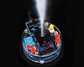
The photo below shows the end result of a few hours of tinkering. The electronics are mounted on a round circuit board with a diameter of 6 cm. This PCB is enclosed between two round plexiglass plates with the same diameter. At the centre of this construction is a black holder containing a piezoceramic transducer at the top and a 6.5 cm long wick at the bottom that sucks the water to be atomised from a glass.
To the right of this holder, you can see a small plug-in circuit board in the photo below. This contains an OLED display on which you can see some data from the internal sensor.
The device is powered by 5 Vdc via a USB cable with a micro-USB connector and consumes approximately 300 mA.
 |
| The end result of this construction kit. (© Banggood) |
Suppliers and prices
According to our internet search, this construction kit with code HU-073 was developed by the Chinese company Hxfbai. It is sold at various prices on almost all well-known internet platforms:
- ICStation: $ 8.99
- Amazon: € 14.99
- AliExpress: € 8.63
- Banggood: € 9.23
Delivery of the kit
All parts are delivered in a plastic bag. The IC socket and the DIL IC are attached to a piece of Styrofoam. The fragile circuit board with the OLED display is in a small plastic box inside the bag, see the inset photo in the image below. Neat, just as it should be!
 |
| Delivery of this DIY kit. (© 2025 Jos Verstraten) |
The supplied components
In the photo below, we have gathered all the components that are part of the package. Next to the round circuit board, you can see the small plug-in circuit board of the OLED display. The two brown round discs form the housing of the whole unit. To the right of this is the wick with the piezoceramic transducer, which atomises the water sucked up by the wick. The tiny component next to the four resistors is an SMD MOSFET.
 |
| The supplied components. (© 2025 Jos Verstraten) |
The manual
The kit comes with a very brief two-page assembly description with tiny photos.
 |
| The second page of the manual. (© 2025 Jos Verstraten) |
Fortunately, a much better and more comprehensive manual can be found on the manufacturer's website:
The circuit board for the HU-073 humidifier
The image below shows the component side of the circuit board for this circuit. It is much clearer than the small photos in the manual and can be printed in A4 format if required.
By the way, in this photo, the only SMD component (Q1) has already been soldered.
 |
| Component side of the circuit board. (© 2025 Jos Verstraten) |
The electronics of the HU-073
The ultrasonic transducer
This consists of a round silicone disc with a diameter of 20 mm. A piezoceramic ring is mounted in this disc, which causes the component to vibrate. A metal disc with a diameter of 16 mm is mounted in the centre of this ring on the front. This is called the 'membrane'. A larger and thicker metal plate is attached to the back, covering the entire piezoceramic disc, but leaving a small gap between the two discs through which water can flow.
 |
| This small component atomises the water. (© 2025 Jos Verstraten) |
No fewer than 740 microscopic holes have been made in the small metal membrane on the front. These have a diameter of only 5 μm. We placed the transducer under our microscope. You can see the result in the image below. It is through these holes in the membrane that the water fog is emitted.
The rear of the transducer must be in contact with water, the output is greatest when the transducer floats on the water surface. In practice, this is of course hardly feasible, which is why, in a practical design, you must use the wick to suck the water from a supply vessel and bring it into contact with the underside of the transducer.
The front of the transducer is referred to in technical jargon as the 'spray port' and the rear as the 'absorbent port'.
 |
| The 'spray port' under the microscope. (© 2025 Jos Verstraten) |
A quick and impressive test
It is amazing how much water mist comes out of this small component. After the circuit board was fully assembled, we glued the transducer to the bottom of a small dish (with a small gap, of course). We then filled this dish with a little water until the bottom of the transducer was just below the water surface. And then we turned on the power! To make the result very clear, we filmed it in a completely darkened room with special lighting, so you can clearly see the water mist produced. Quite impressive, isn't it? So much mist from such a small component!
Of course, the mist is much less intense when you combine the transducer with a wick, as in this kit. After all, the wick cannot supply the necessary amount of water quickly enough to generate that impressive amount of mist.
How does it work?
Naturally, we are curious to know how such a small disc is capable of emitting such a powerful jet of water mist. The figure below explains how this works. The electronic circuit supplies a kind of square-wave voltage to the transducer. The upper metal membrane, with its thin coating of piezoceramic material, vibrates at the frequency of the signal. Because the lower metal plate is larger and thicker, it remains immobile.
There is water between the two metal plates, which can flow in and out of the cavity between them through the gap between the lower plate and the piezoceramic disc. Although this is obviously very little water, on a microscopic scale it forms an enormous and heavy pool.
The figure below shows a single microscopic hole in the membrane. When this membrane moves upwards as a result of the expansion of the piezoceramic disc, it sucks some water into the hole. When the membrane moves downwards again a moment later, the water in the hole cannot follow this rapid movement. The mass and associated inertia of the water between the two metal plates prevents this. The result is that an extremely thin jet of water is ejected with great force through the microscopic hole. All these thin jets of water break up into microscopic droplets of water, which form the mist that escapes from the transducer.
 |
| The operation of the transducer. (© 2025 Jos Verstraten) |
The climate sensor
The sensor used in this kit to measure temperature and relative humidity is a DHT11 from the Chinese company Aosong, currently the cheapest sensor on the market. The DHT11 contains two sensors and a microcontroller that converts the data from the sensors into digital signals.
The DHT11 contains a thermistor with a standardised resistance of 100 kΩ for measuring temperature and a resistive humidity sensor of the HR202 type. This is a sensor that uses a relatively new technology. Two comb-shaped electrodes, with the teeth interlocking, are mounted on a base plate made of an organic material composed of macromolecules. Due to its large molecules, the organic material quickly absorbs moisture from the ambient air. The resistance of the material depends on the relative humidity of this air. This resistance is measured by applying an AC signal across the two electrodes. The measured resistance of both sensors is sampled once every two seconds and converted into two eight-bit words. These four bytes are supplemented with a checksum byte. These five bytes are sent in sequence on command.
 |
| The climate sensor used. (© Aosong) |
The HU-073 schematic diagram
The figure below shows the complete schematic diagram for this kit. In the upper left corner, the +5 Vdc enters via the micro-USB connector P1. The wiring of the on/off switch SW1 is somewhat unusual. In the lower position, the +5 Vdc goes to the VCC of the circuit via contacts 2, 3, 5 and 6.
The piezoceramic transducer is connected to connector P3 and is in series with coil L1 on VCC. The PWM output of microcontroller U1 switches this series connection via MOSFET Q1 at a certain frequency to ground. The coil, together with the transducers own capacitance, causes signal oscillation, which increases the power delivered by the transducer.
The four pins of the DHT11 sensor are connected to connector U2. The DATA output goes to the microcontroller U1.
The OLED board is connected to the circuit via connector OLED1. The SCL and SDA pins also go to U1.
 |
| The complete circuit diagram. (© Hxfbai, edit 2025 Jos Verstraten) |
Building the HU-073 humidifier
Assembling the circuit board
The figure below shows the silkscreen print of the circuit board.
 |
| The circuit board layout. (© Hxfbai) |
The most convenient order for assembly is:
- The SMD transistor AO3400. Our package contained two of these.
- The 100 kΩ resistor R7.
- The 1 kΩ resistors R4 and R6.
- The 100 Ω resistor R8.
- The micro-USB connector P1.
- The IC socket for U1.
- The three identical capacitors C3, C4 and C5 with code 104.
- The LED LED1, the long connection is the plus.
- The two-pin connector P3. Note the position, the side with the slot must face outwards.
- The sensor U2, whose connecting wires you must first bend at a 90° angle so that the side with the holes is at the top.
- The four-pin connector OLED1.
- The coil L1 with the long connecting wire in the PCB-pad closest to the text '3400' on the circuit board.
- The two electrolytic capacitors C1 and C2. Pay attention to the polarity.
- The push button switch SW1.
- The four push buttons switches KEY1 ~ KEY4.
- Mount the five buttons on the switches.
- Mount the IC in the socket U1, paying attention to the position.
 |
| The fully assembled circuit board. (© 2025 Jos Verstraten) |
Assembling the OLED circuit board
Mount the four-pin male circuit board header on the back of the circuit board and solder the four pins to the front. Plug the circuit board into the four-pin connector OLED1 on the base circuit board.
 |
| Preparing the OLED circuit board. (© 2025 Jos Verstraten) |
Installing the circuit board in the housing
Now the eight spacers and eight bolts come in handy! The photo below provides all the information you need to complete this step of the construction process.
 |
Installing the circuit board in the housing. (© 2025 Jos Verstraten) |
Assembling the transducer and the wick
Take out the two black half-holders and assemble the transducer in the round cavity at the top. Make sure that the side with the red wire soldered to it is at the top, as shown in the photo below. Feed the two wires through the small opening in the holder and click the two halves together.
Then feed the two wires from the transducer through the central hole in the upper part of the housing and click the connector into P3. Push the transducer holder through this hole until it clicks into place. Saturate the wick with water and push it into the bottom of the holder until the wick rests on the bottom of the transducer.
 |
| Mounting the transducer in the holder. (© 2025 Jos Verstraten) |
Working with the HU-073 humidifier
Important preliminary note
According to the manual, the transducer may become defective if you allow it to operate for too long without water supply. Therefore, before you start playing around with the device, always place the moistened wick in the transducer holder.

Setting the language
After connecting the device to the 5 Vdc power supply and pressing the SW1 button, the information below will appear on the display. You can use the KEY3 and KEY4 buttons to select Chinese or English as the language. Confirm with KEY1.
 |
| Setting the language. (© 2025 Jos Verstraten) |
Installation
Find a glass with a diameter slightly smaller than 6 cm. Fill it with water. Place the HU-073, with a well-moistened wick, on this glass.
 |
| The HU-073 at work. (© Taobao.com) |
The display
After switching on the device, the display shows the information below. Large digits show the current temperature (°C) and relative humidity (%RH), while smaller digits show the desired humidity, the programmed operating time and the time remaining.
 |
| The information on the display. (© 2025 Jos Verstraten) |
The function of the KEY1 button
Pressing this button briefly starts or stops the device from producing water spray. The symbol in the middle of the display appears when the atomiser is in operation.
Setting the menu functions
Press the KEY2 button briefly to display the menu. Use the KEY3 and KEY4 buttons to scroll through the five options. Press KEY1 to activate the selected option. Use KEY3 and KEY4 to adjust the value of the option. Press KEY1 again to confirm your setting.
 |
The five options in the menu. (© 2025 Jos Verstraten) |
Press KEY2 to return to the menu. Once all options have been programmed, press KEY2 again to exit the menu.

HU-073 humidifier kit