|
You can use it to set paper and matches on fire, to ignite fireworks, fire rockets, shooting carbide (Dutch tradition!) and explode hydrogen gas balloons. And it costs less than three euros! |
Introduction to the HV-1 'High Voltage Lighter Kit'
What is it?
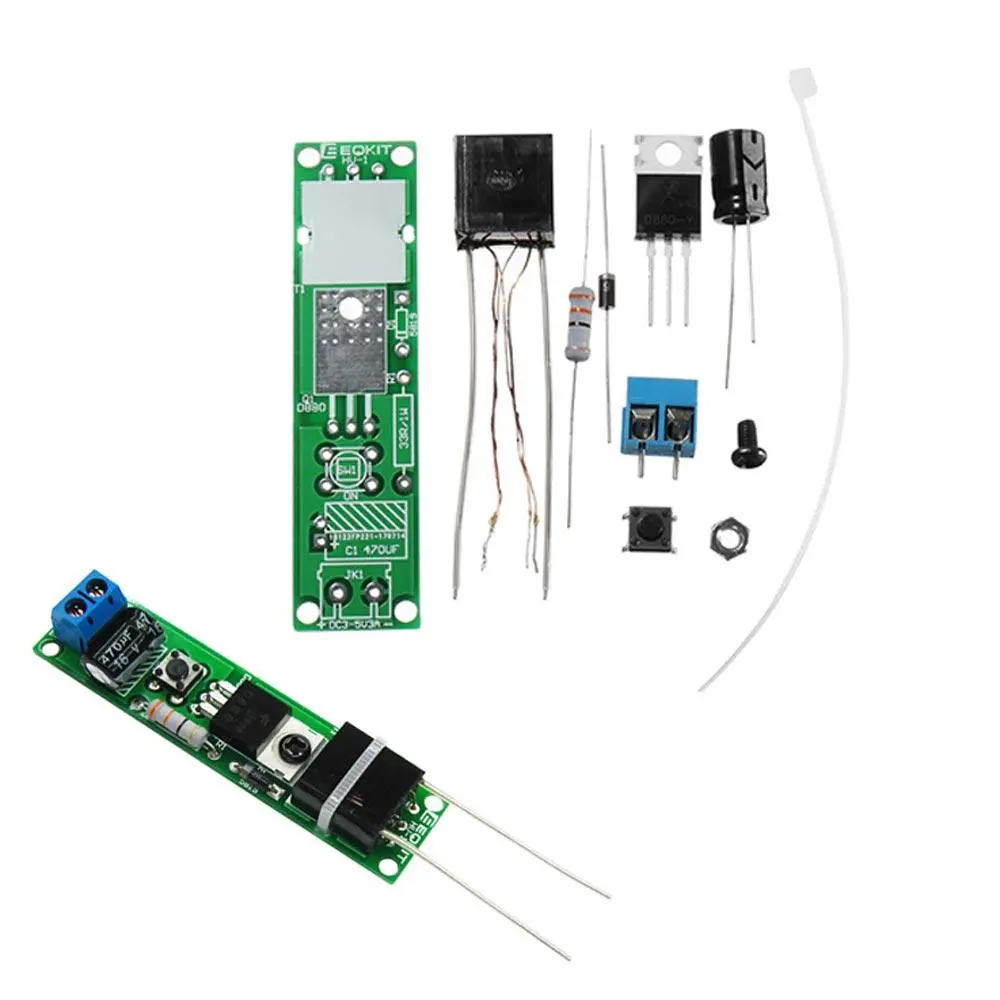
This kit contains only six electronic parts and is on a 53 mm by 18 mm PCB. You pay less than three euros for it on AliExpress. But what does it do? If you connect the board to a DC voltage of at least 3.5 V and at most 5.0 V, you can make an electric arc of up to 10 mm. This electric arc is very hot and you can use it to remotely ignite anything that is likely to catch fire. If, for example, you place the wick of a piece of fireworks between the two electrodes and activate the PCB, the wick will be ignited. Whether it has any useful applications? Perhaps not, but it is a fun and inexpensive toy and it is fascinating to experience how a few electronic parts are able to generate a voltage of around 15,000 V.
The electric arc is of course created between the points of the two electrodes that you see on the right in the photo below. You can replace the pushbutton with two wire bridges and activate the electric arc by switching on the power supply of the PCB remotely via a long wire.
 |
| The result of half an hour's tinkering. (© 2021 Jos Verstraten) |
Who designed it?
As so often with Chinese kits, this one is offered under different names and at different prices. A Google search reveals that there are at least two versions for sale that differ in one detail. The cheapest versions are identical to the photo above. On the slightly more expensive versions, an additional electrolytic capacitor is inserted between the power supply connections.
As manufacturers, we find names such as Haodiy, Eeqkit and YiQi. The model delivered to us via AliExpress by IC GOGOGO Store comes, according to the description, from Haodiy.
The quality of the delivery
The kit is delivered in an air cushion envelope containing a plastic bag with all parts and one sheet of A4 as construction instructions.
 |
| Delivery of the kit. (© 2021 Jos Verstraten) |
The quality of the components
Except for the transformer, the quality is excellent. An SMD version of the famous 2N3055 transistor is supplied. We can be less satisfied about the quality of the transformer. Although we of course realise that it is impossible to supply a professional ignition transformer for such a low price (€ 0.37 bought separately!), the quality could have been better. This 14 mm by 14 mm by 7 mm transformer has two primary low-voltage windings and a secondary high-voltage winding. The latter is well finished with two solid wires. The way in which the winding wires of the two primary windings have been brought out is beneath contempt. The very thin winding wires come out without any support directly from the casting resin with which the little transformer is filled.
You must remove the insulation from these four wires with a sharp knife or sandpaper. If you don't do it very carefully, you may break one of the four wires where it leaves the casting resin. Then the transformer is unusable. A construction with four PCB-pins would not have cost so much extra, would it?
 |
The electronic components supplied. (© 2021 Jos Verstraten) |
The printed circuit board
The figure below shows the two sides of the double-sided PCB. The transformer is mounted on the large white area. Two rectangular holes have been made in the PCB above and below this surface. The intention is to put a tiewrap (supplied) through these two holes to fix the transformer on the PCB. However, this will result in a rickety construction with a transformer that rattles a bit and the risk that one day one of the four winding wires will break. It is better to mount the transformer with a drop of cyanoacrylate glue on the PCB.
 |
| The two sides of the PCB. (© 2021 Jos Verstraten) |
The manual
This is a real joke! It comes with a single-sided sheet of paper containing only Chinese text, the schematic and a picture of the assembled PCB. Fortunately, we found an English step-by-step manual on the Internet, which we have saved for you on our own account on Google Drive:
➡ HV_1_Arc_Ignition_Lighter_Manual.pdf
Although this manual is about the extended version with an extra electrolytic capacitor and a standard 2N3055, it can also be used for the version without capacitor.
|
 |
| The Chinese manual that is delivered with our kit. (© 2021 Jos Verstraten) |
The electronics of the circuit
The circuit diagram
This is of course the simplicity itself and is represented in the figure below. The diode D1 is a FR107, a so called 'fast recovery diode'.
 |
| The schematic of this simple kit. (© 2021 Jos Verstraten) |
How the circuit works
The oscillogram below shows what happens the moment you press the push button (START). The yellow trace represents the voltage on the collector of the transistor. The blue trace gives the voltage on the base of the same component.
Before the 'START' moment, the collector is obviously at the supply voltage and the base at 0 V. You can see this by the arrows on the left of the screen. At the moment you press the pushbutton, a large current flows through winding 3~4, diode D1 and resistor R1 in the base of the transistor. The transistor is driven into saturation. You can see in the oscillogram that the base voltage goes to 0.7 V and the collector voltage goes to 0 V.
At this moment the supply voltage is connected through the conducting transistor directly to winding 1~2. Suddenly, a large current flows through this winding. This current builds up a large magnetic field in the transformer. This field induces a voltage in windings 3~4 which ensures that the base voltage remains positive. You can see that the base voltage even increases a little, the transistor remains in saturation.

The base current reduces the field in the transformer. After a certain time, the base voltage drops below the conduction value. The transistor now goes to the non-conductive state. However, the transformer resists this current change by generating a very high reverse voltage in winding 1~2. As the oscillogram shows, this voltage has a value of 50 V. It is this voltage peak that generates a very high voltage pulse of (according to the manufacturer of the transformer) 15,000 V in the secondary winding 5~6 of the transformer. This voltage is responsible for the creation of the electric arc between the points of the electrodes connected to the secondary winding.
As can be seen from the oscillograms, the time between two pulses is approximately 40 μs, which corresponds to a frequency of 25 kHz. The electric arc is thus maintained.
 |
| The voltages on the collector and the base of the transistor. (© 2021 Jos Verstraten) |
Building this 'High Voltage Lighter'
Soldering the PCB
This is of course no problem for the experienced hobbyist. Start by tinning the two pads on which the emitter and the base of the transistor should be placed. Then solder these two connections to the pads. Make sure that the transistor is placed so far to one side that there is enough free copper left at the other side for soldering the collector to the large square pad on the PCB. Continue the assembly with, in this order, the resistor, the diode, the screw terminal and the push button.
Mounting the transformer
This is the only point that requires attention and caution. As you can see in the picture below, you have to push the four thin wires of the two primary windings through the three holes 1, 2 and 3 of the PCB in a specific way. Two wires are already connected and you should push them through the middle hole (2). The remaining thin winding wire should go through the left hole (3), the remaining thick winding wire through the right hole (1).
Successful? Then use a drop of cyanoacrylate glue to fix the transformer on the PCB.
Next, turn the PCB with the solder side up, bend the winding wires 90° so that they lie flat on the three copper pads. Use a very sharp knife, preferably one of those surgeon's knives with a round cutting edge, and scrape the lacquer off the four winding wires. When this side is finished, bend the wires to the other side and scrape the lacquer off the other side of the wires too.
Finally, solder the four wires to the three pads.
 |
| Connecting the four winding wires of the transformer to the PCB. (© 2021 Jos Verstraten) |
The HV-1 'High Voltage Lighter' in practice
The circuit appears to work very well. Connected to a voltage of 5 Vdc, you can set the points of the two secondary electrodes six millimetres apart and create a nice, stable electric arc. At this supply voltage, the circuit consumes a current of 3.1 A. This means that no less than 15 W is dissipated in the transistor and the transformer!
So it is obvious that you cannot press the push button for more than ten seconds. However, that is sufficient to ignite something that is between the electrodes. The transformer and the transistor become hot very quickly and if you let the circuit operate for too long, these components will be destroyed.
The temperature generated in the electric arc is impressive. We held a type-K thermocouple (chromel-alumel) in the arc and it became red hot after only a few seconds. Our meter indicated a temperature of 1,080 °C.

10 pieces HV-1 High Voltage Lighter Kit