|
Besides the XR2206, the ICL8038 is the second famous IC by which you can quickly design a LF function generator. We tested one of the Chinese kits that is offered for about ten euros. Our opinion: not so good, around an ICL8038 you can design a better function generator yourself! |
Introduction to this ICL8038 function generator kit
What it's gonna look like
In the picture below you can see the result of an hour of tinkering. A case with dimensions of 9.0 cm x 6.0 cm x 1.8 cm containing a complete low-frequency function generator. With four potentiometers you can set the frequency, the duty cycle, the offset and the amplitude of the sine, triangle ans rectangle output signals (rectangle only frequency and duty cycle). In order to save expensive rotary switches, you need to set the frequency range with a jumper:
- 5 Hz to 50 Hz.
- 50 Hz to 500 Hz.
- 500 Hz to 20 kHz.
- 20 kHz to 400 kHz.
With a second jumper you select between sine and triangle on the first output, which is adjustable in amplitude and offset. A rectangle voltage that cannot be adjusted in amplitude is always available at the second output. The two outputs and the ground have been carried out as a three-pole screw terminal block. You can power the device from a mains power supply that supplies a 12 Vdc voltage via a standard 5.0 mm x 2.1 mm connector.
 |
| The result of an hour of tinkering. (© 2019 Jos Verstraten) |
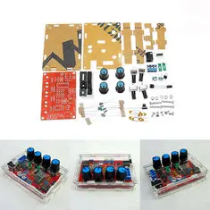
The components are packed in a far too small plastic bag. Everything is crammed into a 15 cm by 10 cm bag, with the result that in our case the connecting pins of a few potentiometers were bent considerably. Fortunately, the IC sockets and the ICs themselves are placed on a piece of foam, so that the pins of these parts can't bend.
") |
| All parts, including the case, are delivered in a small bag of 15 cm by 10 cm. (© 2019 Jos Verstraten) |
Nothing to complain about, all components are of excellent quality and clearly legible coded. Unfortunately, the 78L09 was not included in the package delivered to us. Instead, there was an unknown transistor in the package. That was a bit of a disappointment, because we didn't have such a stabilizer in our parts stock.
Remarkable is that for the three DIL-IC's sockets are included.
 |
| The supplied electronic components are small-scale, but of excellent quality. (© 2019 Jos Verstraten) |
You have to assemble the enclosure out of six panels of perspex that fit around the PCB. The four side panels fit into slots in the top and bottom panels. In the top panel all texts are milled out. The panels are covered on both sides with a self-adhesive protective layer of paper. You can use the enclosure with or without this paper cover. The intention is that you screw the four long self-tapping screws into the bottom panel. That is why only four nuts are supplied.
 |
| The parts from which you should assemble the housing. (© 2019 Jos Verstraten) |
The PCB, measuring 5.0 cm by 8.0 cm, is of excellent quality. Both sides are provided with a soldermask. The soldering pads are very small, so soldering with a very fine tip is absolutely necessary.
 |
| The two sides of the PCB. (© 2019 Jos Verstraten) |
So far, nothing but compliments on this extremely cheap kit. That's different when we take a critical look at the enclosed English building description. A mockery! One single-sided printed A4 sheet with not even the circuit diagram. Through the parts list a text is printed in bold Chinese characters. The manual contains a QR code to an internet page with more information, but scanning this code only results in the message 'The page cannot be found'.

The circuit diagram
Fortunately, it is not difficult to follow the trace pattern on the PCB and convert it into a circuit diagram. The result is shown in the figure below. The first thing that strikes you is that the designers in several places deviate from the schematic prescribed by the manufacturer of the ICL8038.
The frequency range is selected by switching one of the capacitors C3-C4-C5-C6 to ground via the jumper JP2. The frequency in the selected band is set with the potentiometer R4 (FREQ). With the potentiometer R1 (DUTY) you can set the time symmetry of the output signal. The network R2-R10-R3-R9 is used to minimize the distortion on the sine wave. The square wave is available on pin 9. This is an open-collector output that is externally connected to the resistor R11 and goes directly to the output JP3. The triangle on pin 3 and the sine on pin 2 are connected to the jumper JP1, which allows you to set the desired signal shape. The circuit around the ICL8038 is powered directly from the supply voltage you connect to the PCB, +12 Vdc.
The output circuit of the sine and triangle is composed of two op-amp's in a TL082. These circuits are fed symmetrically from two voltages of ±9 Vdc. Thanks to this symmetrical power supply, you can make the triangle and the sine waves symmetrical with respect to the ground without the need for capacitive coupling. This symmetry can be set with the potentiometer R6 (OFFSET). Finally, the signal is controlled in amplitude with the potentiometer R5 (AMP).
This output circuit is quite remarkable and the author of this article would think of a completely different solution for it. We were very curious about the performance of this piece of electronics!
 |
| The circuit diagram of this function generator. (© 2019 Jos Verstraten) |
The figure below reveals the power supply. The 12 V of the mains power supply is decoupled with C10 and powers the ICL8038. From this voltage a positive voltage of 9 V is derived by means of a 78L09. With an ICL7660S converter, the negative supply voltage of -9 V is generated from this voltage. That works very well. In our circuit, the voltages from this circuit were almost symmetrical: +8.96 V and -8.65 V.
 |
| The schematic of the power supply for the generator. (© 2019 Jos Verstraten) |
The manufacturer promises the following specifications for this kit:
- Frequency range: 5 Hz ~ 400 kHz in four ranges
- Output signals: sine ~ triangle ~ rectangle
- Duty-cycle rectangle wave: 2 % ~ 95 %
- Distortion sine wave: 1 % max after adjustment
- Linearity triangle wave: 0.1 % max
- Temperature drift: 50 ppm/℃
- Offset: -7.5 V ~ +7.5 V
- Amplitude sine and triangle waves: 0.1 Vpeak-to-peak ~ 11.0 Vpeak-to-peak
- Amplitude rectangle wave: 12 V constant
- Power supply: +12 Vdc (+15 Vdc max)
- Current consumption: 20 mA
- Dimensions: 88.2 mm x 61 mm x 18.5 mm
- Weight: 82 g
The construction of the function generator
Assembling the PCB
The soldering of the PCB will not cause any problems for an experienced hobbyist. Remember that you need to attach a very fine point-shaped tip to your soldering iron, otherwise you will definitely make a few unwanted soldering bridges.
 |
| The fully assembled circuit board. (© AliExpress) |
The intention is to screw the PCB onto the bottom panel of the enclosure with the four bolts and nuts supplied. This is not possible, the supplied bolts are too short. So use longer bolts and put 2 mm thick nylon rings between the bottom of the housing and the PCB. This way there is room for the solder on the pads. The advantage is that the underside of the housing does not bend when you tighten the bolts.
Afterwards, lock the four side panels into the slots in the bottom and attach the front panel to the sides. With the four long bolts you can now screw the whole device in place. These special bolts screw themselves into the small holes in the bottom panel of the housing.
Testing the function generator
The frequency range
According to the specifications, this generator would generate signals with frequencies from 5 Hz to 400 kHz in four ranges. However, if you turn the potentiometer 'FREQ' all the way to the left, the output signal will be lost. You have to rotate it about ten degrees before the device generates signals. In the table below, the specified four frequency ranges are compared to the values measured.
 |
| The measured four frequency ranges. (© 2019 Jos Verstraten) |
Pin 9 in the ICL8038 is connected to an open-collector transistor. In the schematic of this kit, this semiconductor is connected to a collector resistor R11 of 4.7 kΩ. This output is offered directly to the 'SQUARE'-output of this device. Of course we are curious about the rise time of the output signal. In the oscillogram below, we have shown this parameter at the maximum frequency of 378 kHz that our kit provides.
For this oscillogram we have to note that we have measured with a compensated 1/10 probe, so that the output is loaded with a very small capacity. If you measure the square wave directly, the rise time is a lot worse.
 |
| The rise and fall times of the 'SQUARE' output at the maximum frequency. (© 2019 Jos Verstraten) |
This symmetry setting makes sense mainly at the 'SQUARE' output. In the oscillograms below you can see how the position of this potentiometer affects the output signal. The basic setting was the 'DUTY' potentiometer in the middle position and the 'FREQ' potentiometer set to 10 kHz. This results in a nice symmetrical square wave. Unfortunately the 'DUTY'-potentiometer not only changes the symmetry of the signal, but also the frequency. Turned completely counterclockwise, the output signal disappears. The first signal that appears when turning this potentiometer very slowly is a narrow positive pulse with a frequency of only 2.0 kHz and a duty cycle of 6.5%, see left oscillogram. In the rightmost position, the generator delivers a signal with a frequency of 12.5 kHz and a duty cycle of 91 %.
That's not right! With a good duty control, the frequency of the signal would remain constant and only the time symmetry would vary. NOTE: The two oscillograms do not have the same time base setting. Left 80 μs/div, right 20 μs/div.
 |
| The output signal at the two outermost positions of the 'DUTY' potentiometer. (© 2019 Jos Verstraten) |
For some reason the triangle, named 'TRI' by default on all function generators, is called 'TAI' here.
At about 10 kHz with the potentiometer 'OFFSET' in the middle position and the potentiometer 'AMP' fully open, the generator delivers the output voltage of the oscillogram below. So there is little symmetry in this signal and also the signal gets blocked against the positive supply voltage. This too is a very bad performance. With the potentiometer 'OFFSET' in the middle position, the signal should be completely symmetrical with respect to the zero axis.
By rotating both potentiometers you can get a nice symmetrical signal out of the device, but this adjustment does not run smoothly. The position of the 'AMP' potentiometer also affects the symmetry of the signal.
 |
| The triangle at maximum 'AMP' and 'OFFSET' in the center position. (© 2019 Jos Verstraten) |
 |
| The most ideal 350 kHz triangle we could make out of this generator. (© 2019 Jos Verstraten) |
The sine is derived from the triangle. If you look at the oscillogram above, it is clear that you cannot expect much good from the sine at the maximum frequency of 350 kHz. That's why we tested the generator for sine wave at a frequency of only 20 kHz. With the two potentiometers R2 and R3 you can adjust the sine for minimal distortion. If you do not have a harmonic distortion meter, you should do this visual on the screen of your oscilloscope. As the oscillogram below shows, there is a persistent residue of the triangle on the tops of the sine wave that cannot be removed. The specification 'Sine distortion: 1 % max. after adjustment' is therefore completely unrealistic.
 |
| At 20 kHz there is still a lot of distortion on the sine wave. (© 2019 Jos Verstraten) |
Our opinion on this function generator kit
With a little more attention and time in the design phase of the circuit around an ICL8038 it is possible to design a much better function generator. Especially the circuit around the double op-amp TL082 is quite useless and could have been much better. The 'AMP' setting greatly influences the 'OFFSET' setting, which is not the intention and which could have been avoided with a slightly different design.
Our advice: buy this kit for the parts and start your own alternative design using the countless schematics that you can find on Google. We guarantee you that you will design a function generator with better specifications.

ICL8038 function generator kit