|
With this cheap kit you can build a simple PIR alarm to secure your doors, carport and garden. If someone moves within the range of the device, an audible alarm will sound for ten seconds. |
Introduction to this infrared alarm
Nameless and unbranded
As so often with such cheap Chinese products, this kit is completely nameless and unbranded. You can find it by googling on 'infrared electronic alarm kit' or 'infrared electronic diy learning kit'. The price is € 6.00 at the well-known Chinese sites such as Banggood and AliExpress. If you order five kits, the price even drops to € 4.50 each. For that money you get a complete infrared alarm with a PIR detector and a built-in alarm generator, see the picture below where we present the end result of your tinkering.
The dimensions of the alarm are 9.0 cm by 5.5 cm by 3.5 cm. You can mount the device with the bracket on a wall and rotate it in all directions. The alarm is powered by four 1.5 V AAA batteries and has a slide switch to turn it on and off. The device does not make a deafening noise, but the alarm is loud enough to discourage unwelcome visitors.
 |
| The result of a few hours of tinkering. (© 2020 Jos Verstraten) |
The scope of delivery
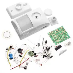
In the photo below we present you all the parts supplied. The quality of the electronic components is good. However, for a kit that is recommended by the vendors as an 'educational kit' one could have chosen for larger components. For example, the supplied resistors are extremely small, probably 1/8 watt. Delivery of 1/4 watt resistors would hardly have influenced the price, but might have been less discouraging for the do-it-yourselfer who wants to solder a PCB for the first time.
 |
| The electronic components of the kit. (© 2020 Jos Verstraten) |
A very poor building description
If the vendor does what he has to do, a good building description is part of a diy kit. Unfortunately this is disappointing. One sheet of A4 is included with some Chinese text and a few drawings and unclear pictures. This kit is offered as a 'diy learning kit' so suitable to make an absolute beginner enthusiastic about electronics as a hobby. With such an inadequate building description it will unfortunately not work, on the contrary! It has to be admitted that all suppliers mention that there is no proper description included: 'We do not supply manuals, pay attention to this before you buy it, sorry for all the inconvenience'.
That's why in this article we will go into the construction of the device a little more extensively than we normally do.
 |
| The sheet of A4 paper that comes with this kit. (© 2020 Jos Verstraten) |
The printed circuit board
The supplied PCB is single sided and of excellent quality. The solder pads are big enough not to scare someone who starts learning how to solder electronic circuits.
 |
| The two sides of the PCB. (© 2020 Jos Verstraten) |
The schematic diagram of the infrared alarm
We have taken the trouble to redraw the messy scheme on the sheet of paper more clearly. The PIR sensor Y1 is powered via resistor R1. Capacitors C2 and C3 decouple this supply voltage. The output signal of the sensor goes via resistor R7 (note, only 2.2 Ω) to the input of IC1. This is a BISS0001, an IC specially designed for processing the signals from PIR sensors. The parts around this IC set the internal amplifiers and filters.
The output signal of this IC on pin 2 controls the power supply connection of IC2 via resistor R13 (also only 2.2 Ω). In fact, IC2 is not an IC, but an extremely small module that generates the typical alarm sound. This signal is amplified via the two transistors VT1 and VT2. The load of both transistors consists of a few windings of coil L1. The signal in those windings generates a fairly large signal over the complete coil. This signal is used to power the piezo-ceramic resonator BL. This produces the alarm sound.
 |
| The schematic diagram of the infrared alarm. (© 2020 Jos Verstraten) |
How it works
Heat is energy
Every body that is warmer than the absolute zero temperature of -273.15 °C emits energy in the form of infrared radiation that is invisible to humans. The amount of radiation depends on the temperature difference and the size of the object. This means that a human being emits energy in the form of infrared radiation. The wavelength of this radiation is around 10 μm. This is a fortunate physical fact, because a 100 W incandescent lamp naturally also emits infrared energy. However, the wavelength of this radiation is a factor of ten lower, i.e. around 1 μm. The sun's infrared radiation is also far beyond the range of human radiation. In this way, you can very easily detect the infrared radiation emitted by a a person. It suffices to develop a detector with a maximum sensitivity of around 10 μm.
The principle of pyroelectric detectors
The principle of pyroelectric detectors (PIR) is that the infrared radiation heats up the detector. This heating up results in certain charge differences in the detector, which in turn can be converted into voltage differences. Although a human being emits an average of 100 W of infrared energy, this energy will spread very quickly in space. As a result, in most cases the temperature rise of the detector is only 0.02 °C. Nevertheless, the developed detectors are sensitive enough to detect this very small temperature difference.
Two work better than one
Such pyroelectric detectors can not detect the presence of a person. This is due to the extremely high sensitivity of such detectors. If you only use one detector, it would respond to every hundredth degree change in ambient temperature and there would be no reliable detection at all. This is why a pyroelectric sensor is composed of two pyroelectric detectors switched in anti-series, see figure below. It is ensured that the two detectors are thermally coupled very closely, so that one can be sure that they are both at the same ambient temperature. In this way, the influence of the varying ambient temperature is completely eliminated. It will be clear, however, that the radiation from one person will now also affect both detectors and will not result in a resulting signal. Something else therefore needs to be invented, namely a special optic for the detector.
Because the detectors have a very high impedance, it is necessary to use an impedance transformer. In most cases this consists of an FET follower and the output voltage is taken from the source.
 |
| The electrical diagram of a pyroelectric sensor. (© 2020 Jos Verstraten) |
The fresnel lens
A PIR sensor is only intended to give a signal if a person moves through the sensor's 'field of view'. This was solved by including a segmented lens in front of the PIR sensor, also known as a 'fresnel lens'.
The fresnel lens will focus the infrared radiation in a very special way on the two pyroelectric detectors connected in anti-series. How this works is schematically shown in the figure below. If a person moves through space, the fresnel lens will ensure that the radiation emitted by this person is successively directed to one or the other detector. The result is that there are small temperature differences between these detectors. These generate small charge differences, which in turn are converted into small voltage differences by the built-in electronics. When a person moves through the room, the PIR sensor will therefore generate a small AC voltage signal, as shown in the bottom graph of the image. The system is so sensitive that even the slightest movement of a head, hand or leg is registered.
 |
| The fresnel lens concentrates the radiation alternately on one of the two pyroelectric detectors. (© www.elettronicanews.it) |
Building the infrared alarm
Good quality parts, but very small
As already written, the delivered parts are of a good quality, but very small. For example, the supplied resistors are only three millimeters in size! To decipher the colour code, a magnifying glass is an absolute necessity. To be sure, check the value of the resistors with your multimeter. Precise work when soldering the components on the PCB is absolutely necessary!
 |
| The very small resistors. (© 2020 Jos Verstraten) |
Assembling the PCB
Start by soldering the small wire bridge J1 above the PIR detector Y1. Use a piece of one of the connecting wires of a resistor.
Continue by soldering the four horizontal resistors R3, R6, R13 and R15. Pay attention to the value of R13! This is 2.2 Ω with the colour code red-red-gold. Next, solder the ten vertical resistors into the PCB. Note R7, which is also 2.2 Ω.
Then insert the seven nF capacitors. These are the small brown discs with values like 102, 103 and 104. Now it is the IC BIS0001's turn, you first have to bend the pins a bit inwards. Continue with the switch K1, cut two millimetres from the switch shaft.
Pay attention to the correct position of the five electrolytic capacitors (the black cylinders). The shaded connection on the silkscreen on the PCB is the negative connection. While soldering the two transistors, make sure that one is a 9014 and the other a 9013. The wires of the pyroelectric detector Y1 must be pushed all the way through the PCB so that the sensor rests on the PCB surface.
When fitting coil L1, you must pay attention to the two wires with a low resistance and those with a high resistance. Measure this with your multimeter! The two wires with a resistor of about 17 Ω must be mounted in the holes connected with a blue line on our PCB drawing. This line is not on the PCB, we have drawn it on our picture of the PCB to clarify this.
The photo below gives you an impression of the completely assembled print.
 |
| The fully assembled PCB. (© 2020 Jos Verstraten) |
Assembly of the IC2 module
If all goes well, you now have one resistor of 100 kΩ left. You need to solder this to the small PCB of the sound generator module IC2, as shown in the picture below. Then insert this PCB into the slot in the larger PCB and solder the four soldering strips at the edge of the PCB to the four soldering strips next to the slot.
 |
| Soldering of the last resistor on the module IC2. (© 2020 Jos Verstraten) |
The wiring of the main circuit board
The package contains two short and two long wires. Solder the two short wires in the holes '+' and '-' on the PCB, the two long ones in the holes 'BL' next to the coil L1.

Mounting the mechanical parts in the housing
Next, you must fit the mechanical parts shown in the photo below into the housing. Attach the lens foil [1] with the rippled side outwards via the grey yoke [2] in one half of the housing. Press the piezo-ceramic transducer [3] into the same half of the housing. Mount the four battery springs [4] and the battery clamp [5] in the other half of the housing.
 |
| Mounting the mechanical parts in the housing. (© 2020 Jos Verstraten) |
Installing the PCB
You can then mount the PCB in one half of the enclosure using the three self-tapping screws supplied. When doing so, you must mount the loose button of the slide switch over the black shaft of the PCB switch. This button then slides back and forth between the edge of the PCB and the edge of the housing. Place both halves of the housing next to each other and solder the two short wires to the two battery terminals. Pay attention to the correct polarities, plus to plus and minus to minus. Solder the two long wires to the outer and middle electrodes of the piezo-ceramic transducer.
Finally, you can click both halves of the housing together, mount the four AAA batteries and snap the housing into the ball joint of the wall mount.
 |
| Mounting the PCB in the housing. (© 2020 Jos Verstraten) |
The infrared alarm in practice
Activate the alarm
After switching the slide switch to the ON position, the circuit will sound an alarm for about ten seconds. This is a check on the condition of the batteries. According to the data on the internet, this alarm has a volume of 90 dB. This is really not attainable, but the sound is loud enough to discourage an unwanted visitor.
The power consumption
The alarm consumes approximately 50 μA of current when idle and approximately 60 mA when the alarm sounds.
The operating range
In the specimen built by us, the range is more than six metres.

Infrared alarm kit