Introduction to Lianying's J2354 rheostats
The scope of delivery
The J2354 is manufactured by the Chinese Yueqing Lianying Import and Export Trade Co., a manufacturer specializing in the marketing of inexpensive technical equipment for education. The rheostat is delivered in a neat little box with a four page manual with some application examples. Unfortunately, it is written entirely in Chinese, so you won't get much out of it.
 |
| The scope of delivery of the J2354 rheostats. (© 2020 Jos Verstraten) |
Compared to the giant rheostats I remember from the electronics lab of my technical education, the J2354's have modest dimensions: 150 mm x 30 mm x 55 mm, see figure below.
 |
| The dimensions of the J2354 rheostats. (© 2020 Jos Verstraten) |
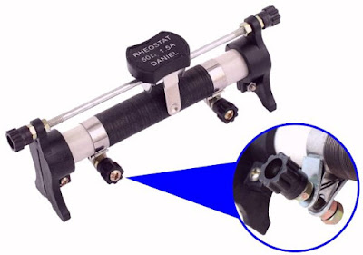
As the picture below shows, this cheap adjustable power resistor doesn't look bad. The resistance wire is wound on a sturdy ceramic cylinder and the slider moves smoothly back and forth over the guide rod. The slide contact is in the form of a fork that makes contact with the resistance wire on both sides. The only annoying thing is that the connections are not provided with 4 mm banana connectors, but with screw connectors, see inset. Replacing these connectors with normal 4 mm banana connectors, so you can connect test leads with banana plugs to the rheostat, wouldn't have been very expensive.
 |
| The appearance of the J2354. (© 2020 Jos Verstraten) |
Unfortunately, the specifications of this rheostat series are treated as if they were government secrets. You only collect some brief data after visiting dozens of sites. It turns out that the maximum power you are allowed to dissipate in these rheostats is 120 W and the maximum voltage you are allowed to put between the terminals is 200 V. This is a theoretical value, because in view of the available resistance values summarized in the table below, you may never or never put 200 V over such a component. On yet another site we learned that the tolerance on the resistance value is ±10 %.
 |
| The available members of the J2354 family. (© 2020 Jos Verstraten) |
Testing the 20 Ω version of the J2354 rheostat
The tolerance on the resistance value
There's not much to test on such a simple component. The most interesting is of course the tolerance on the resistance value and the variation of the resistance in function of the temperature. We ordered a 20 Ω sample for the test. Using a constant current source, we applied accurate currents through the entire resistance of the rheostat and after warming up to the final temperature, measured the voltage across the component. This way the resistance can be calculated quickly using Ohm's law. We also used a thermocouple to measure the temperature of the resistance wire. We did this by clamping the thermocouple under the sliding contact. The results of this tests are summarized in the table below.
 |
| The results of the test of the 20 Ω rheostat. (© 2020 Jos Verstraten) |
The first thing to notice is that the specimen under test, with its room temperature value of 18,50 Ω, is within the given tolerance of ±10 %.
The second is that the resistance has a positive temperature coefficient. The warmer the wire, the higher the resistance. This is to be expected because this is a property of nature. The warmer the material, the more atomic vibrations are created in the material and the more resistance the electrons, which flow through the material, encounter.
The third noteworthy point is the extremely high temperature of the resistance wire at the maximum current allowed to flow through the resistor. Nevertheless, the J2354 keeps very well at this temperature. The ceramic cylinder can easily withstand this temperature and the expansion coefficient of the resistance wire is so low that the windings stay neatly on the cylinder. Because the windings have only a very small contact surface with the construction (the two sliding contacts), the rest of the component remains quite cool. Even after fifteen minutes of a current of 2 A through the rheostat, the temperature in the screw connectors remains limited to 122 °C.
The fourth point is that the specification of 120 W as maximum power is nonsense. If the temperature of the resistance wire already rises to 373 °C at a load of up to 76 W, then it is to be expected that at a load of 120 W, the whole rheostat will work as an electric radiant heater. Don't do that!

The contact resistances
If you put the slider in the extreme left or right position, the rheostat should have a resistance of exactly zero ohms with respect to the left or right connection. This is easy to test by putting the rheostat in these extreme positions, pass a current of 2 A through it and measuring the voltage drop across the contacts of the rheostat. The results:
- Slider contact at the far left: 0.007 Ω
- Slider contact on the far right: 0.006 Ω
Extremely low values, but the measurements have been made twice and give almost identical values.
Our opinion on the J2354 reostat
When we accidentally encountered a picture of this rheostat while surfing and found out the price a little later, our first thought was that we were once again dealing with cheap but unusable Chinese toys. Thinking back on our student years with melancholy led us to order such a rheostat after all. Now that we have tested this one, we don't think about toys anymore. These rheostats are a useful and cheap addition to the hobby lab. Most of the stuff we test will be sold as soon as possible, but we are really going to keep this rheostat!

10 Ohm / 2 A Rheostat

