|
Another 433 MHz wireless switch? Yes, but one with special features. The outdoor range is said to be more than 500 meters and the transmitter is said to be extremely economical. True or false? We investigated. |
Introduction to the King-Serry 433 MHz remote switch
What is it?
This system consists of a number of battery-powered transmitters that, when activated, broadcast a digital telegram on a carrier frequency of 433.932 MHz. This telegram consists of an address code unique to the specific transmitter and a command code ON or OFF. This signal is received by the receiver of the system. This device switches a 230 V/110 V load on or off.
In itself, this is nothing sensational, as there are dozens of similar systems on the market. The fact that we pay attention to this system has to do with a number of special features claimed by the manufacturer.
The unique features of the King-Serry system
According to the manufacturer, this system distinguishes itself from the competition by the following specifications:
- The distance between a transmitter and a receiver can be more than 500 meters in the free field.
- In a building, the range can be more than 50 meters without any problem.
- With its dimensions of 39 mm x 23 mm x 22 mm, the receiver is particularly small and can therefore easily be built into a device.
- Despite the small size, the receiver is equipped with a relay that can switch a load of 1,000 W.
- This relay ensures that you can reliably switch on and off any load without problems.
- The battery-operated transmitters are extremely economical, so that the manufacturer guarantees more than 70,000 switching actions on one battery.
- The transmitters are dust/water-resistant up to an IP value of 54. The first five means that, although the transmitter is not completely dust-tight, it is sufficient not to interfere with the proper functioning of the device. The second four means 'splash proof', no penetration when water is sprayed in all directions at a flow rate of ten liters per minute under a pressure of 100 kPa.
The manufacturer and the sellers
The manufacturer is the Chinese Shenzhen King-Serry Electronics Co. Ltd. from Shenzhen City. However, you will not find the devices under this name in Internet shops. As is so often the case with Chinese products, the manufacturer keeps a low profile. We have found no fewer than six names under which these switches are offered on AliExpress and other mail order companies:
- AivaToba
- NineLeaf
- Mengshen
- Thinkbee
- Geekbes
- Smernit
The last name is interesting because the King-Serry products under this name are offered on AliExpress at prices significantly lower than the deals under the other names.
Overview of the system
In the composition below, we have brought together the various products of the King-Serry system. On the far left you see the only receiver of the system and the only component with a double type number, namely SW-R02 for 230 V grids or SW-R01 for 110 V grids. Next to it are three small wall-mounted transmitters SW-NK1, SW-NK2 and SW-NK3 with one, two and three channels respectively. Next is a wall-mounted transmitter with the standard dimensions that you are used to, and finally two miniature hand-held transmitters with three and one channels respectively.
 |
| The components of the King-Serry system. (© 2021 Jos Verstraten) |
How much does it cost?
The prices are quite different. On AliExpress (search for Smernit), a basic set consisting of a one-channel wall-mounted transmitter and a receiver costs € 18.08. An additional one-channel transmitter costs € 6.43 and an additional receiver € 17.03. These prices are valid in December 2021.
The basic set
To test the system, we order the cheapest basic set. Please note the desired mains voltage when ordering! The set comes in a sturdy unbranded box and contains, besides the transmitter and the receiver, two terminal blocks with handy push-in spring connections and a manual.
 |
| The delivery of the basic set. (© 2021 Jos Verstraten) |
The manual
The manual is an eight-page miniature folded flyer written in reasonable English with such a small font that it is hardly readable for our old eyes. That is why we scanned it and enlarged it to A4 size, see the link below:
➡ King-Serry manual
The wall-mounted transmitter SW-NK1
The appearance
This wall-mounted transmitter is 75 mm high and 47 mm wide and only 15 mm thick. A sheet of double-sided adhesive foam 1.5 mm thick and measuring 68 mm by 40 mm is supplied. This should be used to stick the switch to a smooth surface. Alternatively, the switch has one hole internally with which you can screw the case on the wall.
The front hinges at the top, so you need to press it at the bottom, next to the blue LED, to activate the switch.
 |
| The single-channel miniature wall-mounted transmitter. (© AliExpress) |
The battery in the transmitter
The transmitter is powered by a CR2032 battery. This is present in the device upon delivery. One of the specifications of the system is that this transmitter is extremely low-power. The stand-by current is only 0.01 μA and the blue LED is only activated for 100 ms when you operate the switch. According to the manufacturer, this wall-mounted transmitter can run for ten years on one battery if you operate the switch ten times a day. That's a good thing, because when the transmitter is mounted on the wall, it's not easy to replace the battery!
The inside of the transmitter
In the picture below, the interior of this device is shown. What immediately stands out is the special construction of the antenna. In most similar products, the antenna consists of a zigzag track that is etched onto the circuit board. With the wall-mounted transmitters of the King-Serry system, the antenna takes the form of a sturdy metal wire that is bent into a spiral in the upper half of the housing. The relationship between the length of the antenna and the wavelength of the 433 MHz signal is not very clear, but we assume that the designers have thought about this.
In the middle of the antenna, you can see the mounting hole for screwing the transmitter to the wall. On the right-hand side of the PCB are the two gold-plated pads on which the conductive rubber of the switch presses. There are two chips on the board. The codes are 0B0C6 and WLR03K6. We cannot find any data of both chips. Finally, we detect a crystal with a frequency of 26.2982 MHz.
 |
| The interior of the wall-mounted transmitter. (© 2021 Jos Verstraten) |
The receiver SW-R02
The appearance
The dimensions of this module are 39 mm x 23 mm x 22 mm. On one side, four 70 mm long wires come out of the module and connect the receiver to the mains voltage (red/blue) and to the 230 V/110 V load (blue/brown). On the other side, the antenna comes out of the module, a wire of 17 cm length. This is quite unique, most wireless receivers have the antenna inside the housing. On the top is a small push button that you must press if you want to pair the receiver with one or more transmitters.
 |
| The receiver SW-R02. (© AliExpress) |
A little more about the antenna
As written, the antenna is 17 cm long. This is no coincidence! A rod antenna picks up the largest signal of a certain frequency when its length is equal to a quarter of the wavelength. This is called a 'quarter wave' antenna.
As you may know, the wavelength of a signal is equal to the speed of light divided by the frequency of the signal. Applying that formula to a 433 MHz signal, it turns out that the wavelength of such a signal is equal to 69.28 cm. A quarter wave for this frequency should therefore have a length of 17.32 cm.
A missed opportunity!
One contact of the switch in the relay is internally connected to the mains live wire. The result is that, when the relay is energised, the other contact of the switch is connected to the live and this voltage is applied to the brown wire. This is handy and easy to understand for a non-professional.
However, we would prefer the two contacts of the relay switch to be brought out floating, so that it is also possible to switch devices other than those that are powered from the mains.
The interior of the receiver
The housing cannot be opened, so the saw must be used to carefully free the electronics from the white block. It then appears that there is a lot of electronics present, spread over two very small PCBs.
The basic PCB measures 35 mm by 18 mm and is packed with components on both sides. Perpendicular to this board is a second board measuring 25 mm by 12 mm, on which three chips and some mini-SMDs are located.
The large red/brown component is a 470 nF and 630 V capacitor. In the absence of a power supply transformer, the capacitive impedance of this part is undoubtedly used to reduce the mains voltage to a value that is acceptable for the electronics. The black block is of course the relay. In the receiver that is delivered to us, a Goodsky relay is used with the type number GQ-SH112LM1F. According to the specifications, this relay can switch 10 A at a maximum voltage of 250 Vac over the contacts. The contact resistance is 100 mΩ maximum. The coil voltage is 12 V at a switch-on current of only 16.7 mA.
 |
| The internal of the receiver SW-R02. (© 2021 Jos Verstraten) |
If we turn the PCB upside down, it becomes clear what other electronics can be found there. You can see that the four connecting wires are soldered directly to the pads of the PCB and are led from there directly through the housing. A number of isolation slots have been milled into the PCB between the four pads.
The smallest PCB contains a CMT2210LB. This is a high-frequency receiver of CMOSTEK for the 300 MHz to 920 MHz band to which the antenna is connected. This chip extracts the digital telegram sent by the transmitter from the 433 MHz carrier wave and makes it available on the DOUT pin. The second chip is a T2402A, a 2 kB EEPROM from BrightMoon Semiconductor. The third chip is a PWR01K6, about which we can find no information.
 |
| The other side of the circuit board. (© 2021 Jos Verstraten) |
Working with the system
Connecting the receiver
Use one terminal to connect the mains voltage to the red and blue wires, and the second one to connect the load to the brown and blue wires. It’s as simple as that!
 |
Connecting the receiver. (© 2021 Jos Verstraten) |
Pairing the transmitter and the receiver
This is very simple. When the receiver is connected to the mains, press the small button (the Setting button) on the receiver for at least two seconds. The LED will start flashing. Then press the switch on the transmitter that you want to register. That's it!
You can register up to eight transmitters to one receiver. In this way, it is possible in a system with several receivers, to have them all respond to one 'master' transmitter.

Unpairing a transmitter and a receiver
Keep pressing the switch on the transmitter. After about one minute, the blue LED of the transmitter starts blinking fast, then it blinks slowly eight times, then slowly nine times. Finally, the LED blinks once very slowly. After this you can release the switch of the transmitter. The address of the transmitter is now deleted from the memory of the receiver.
A small test of the King-Serry system
Receiver power consumption when idle
The receiver is continuously connected to the mains voltage and therefore requires a certain amount of power. This power must, of course, be as low as possible. The manufacturer does not provide any information about this important specification and the data on the various shop pages contradict each other. Here and there, an idle power of 0.5 W is mentioned.
We decided to measure this specification ourselves. We measured it by inserting our digital multimeter, switched to alternating current, in the supply circuit to the receiver. We were amazed when this meter indicated an idle current of 34.45 mA. This corresponds, at 230 V, to a power of no less than 7.92 W! Because we cannot believe this, we perform the measurement again, but now with our old, trusted analogue AVO meter. It measures an alternating current of 32.0 mA. Nearly 8 W of power consumption in such a small box would cause quite a warming up. But this is not the case, the receiver remains at room temperature.
Then we think of the large 470 nF capacitor that is prominently present in the receiver and the concepts of 'phase shift' and 'reactive power' come to mind. We connect a resistor of 11.15 Ω (measured a 10 Ω resistor correctly) to the primary circuit and use the oscilloscope to measure both the voltage across this resistor and the voltage supplied to the receiver. The voltage across the resistor is of course directly proportional to the current flow in the circuit. The result is shown in the oscillogram below. The current that the receiver draws from the mains is almost 90° out of phase with the voltage offered to the receiver. The current (yellow trace) is clearly ahead of the voltage (blue trace).
 that the receiver draws from the mains.") |
| The current (yellow) that the receiver draws from the mains. (© 2021 Jos Verstraten) |
The receiver is an almost perfect capacitive load. The oscilloscope measures a voltage drop of 373.1 mV over the 11.15 Ω resistor. That corresponds to a current of 33.5 mA. So the current measured by our multimeters is correct. The power is not a real power in W but, due to the phase angle of almost 90° between the current and the voltage, a reactive power in var or VAR (volt-ampère-reactive) that does not generate heat and that your electricity meter does not register either.
We can therefore conclude that the receiver is indeed drawing almost negligible real power from the grid.
The power consumption of the transmitter
According to the manufacturer, the electronics in the transmitter are extremely economical, so the built-in battery will last for years. We have measured this by replacing the 3.0 V battery by a 3.0 V power supply and inserting our digital multimeter, switched to mAdc range, in its logging mode into the power supply circuit. If we press the switch often enough afterwards, it will undoubtedly happen that the meter logs at that moment and we can read off the current consumption when the transmitter is activated. This turns out to be a current of 7.125 mA. In the inactive mode, the transmitter draws a current of 0.013 μA, negligible indeed!
The indoor range
This is a property that is difficult to assess objectively because it depends on quite a few factors. The number of walls and ceilings between the transmitter and receiver and the material from which these obstacles are made play an important role. It is written that a distance of 50 metres can be covered. In our house, which is 12 m by 10 m and one floor high, we cannot create a situation where there is a problem.
We involve the neighbors' house in our experiment and increase the distance between the transmitter and the receiver to 26 meters, which is the maximum that can be achieved in this situation. Between the transmitter and the receiver there are four thin walls, one thick wall and one ceiling. The system works perfectly.
The outdoor range
In the various advertisements for the system, open field ranges of 400 to even 600 meters are mentioned. If this is true, the King-Serry system would indeed distinguish itself from the competition and fill a gap in the market. We can measure this specification very well. Our house is located directly opposite a T-junction and, as a result, we have an unobstructed view from our front door of a 639 meters straight street. What Google Maps isn't good for! So we install the receiver, antenna bent completely straight, in the open front door and walk with the transmitter down the street, pushing the switch now and then. To our great disappointment, things already go wrong after 144 meters. The lamp connected to the receiver no longer responds....
 |
| Field test of the outdoor range. (© 2021 Jos Verstraten) |
Our conclusion about the King-Serry system
We started this article with the remark 'Another 433 MHz wireless switch? Yes, but one with special features.'
The first special feature is the large outdoor range of 500 metres claimed by the suppliers. Our test shows that this is not true. The range is not much longer than that of most competing products.
The second special feature is the very economical operation of the transmitter, which allows you to work with the built-in battery for years. However, this too is not so special. We have been using for at least twenty years 'KlikAanKlikUit' wireless switches in all kinds of places in our house. The batteries of these transmitters also last at least five years.
So we do not find the King-Serry system so special. As far as price goes, it is between the cheapest and the most expensive systems. A 230 V receiver such as the KR2201-4 may be slightly larger than the SW-R02, but it only costs € 5.53.
However, nothing but praise about the quality of the products. The way the receiver is designed is without a doubt a gem of sub-miniature electronics.
Response of the manufacturer
- 1.
The load you wrote in your blog is 1,000 W. The actual load is divided into three types: capacitive load, resistive load and inductive load. Among them, the capacitive load of our company's receiver can reach 1,000 W, and the resistive load is 1,800 W. In the product manual there are also detailed parameters, which you did not attach, and did not make it clear in the blog. - 2.
Regarding the number of battery on and off, our battery can be turned on and off 300,000 times instead of 70,000 times. The parameters in the manual are also listed in detail. - 3.
The waterproof level has not been tested before, we may only write IP54. If it is a product purchased in the last six months, our manual has detailed the IP66 level. A waterproof level of IP66 is not required for wireless switches, but it can better protect the battery life (our company’s products can reach 8-10 years, or even longer. Because our products are in the 7th year this year, no customer has proposed to replace the battery), and KTNNKG’s products are not waterproof, and their lifespan will be greatly shortened. It is estimated that they will need to be replaced at most 1-2 years. - 4.
Our 86-type wireless switch SW-NK3 and SW-K1 series, the open distance is 400~600 meters, while the indoor and urban environment is generally 30~100 meters, there are detailed parameters in the manual. The distance you tested is up to 144 meters. If you use SW-SK1, it is far beyond the distance (30-50 meters) used in our manual.


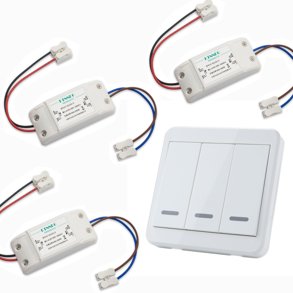
3 Pcs KTNNKG Wireless Light Switch