Introduction to the laser harp DIY kit
What is a laser harp?
A laser harp is a harp whose strings have been replaced by laser beams. Lasers emit very narrow beams of light, and it is in fact obvious to make the comparison with the also very thin strings of a harp. Googling the words 'laser harp' reveals a whole world unknown to us and it turns out that this concept has invaded the dance world. But we don't want to talk about that, we'll stick with the 'real' original laser harp. In the picture below, you can see what such a professional musical instrument, in this example from Mountain Glen Harps LLC, looks like.
 |
| A professional laser harp. (© Mountain Glen Harps) |
How does a laser harp work?
In the lower half of the harp, a number of laser diodes are mounted that radiate perpendicularly and thus parallel to the top. In the upper half, an equal number of photodetectors are mounted, which detect the presence or absence of the laser beams. By interrupting the beams with your hands, you can play the instrument.
In the video below you can see an example, in this case by the builder Glenn J. Hill, and hear how the instrument sounds.
A simple kit and a nice toy for the kids
Now that laser diodes and photodetectors are ridiculously cheap, it is obvious that the idea of the laser harp lends itself to a cheap and simple kit. Leave this to the Chinese! The kit described in this article was developed by Haodiy and is offered through the well-known channels of AliExpress for prices starting at ten euros. To give you an idea of what you should expect from such a kit, we show you the end result of a few hours of tinkering in the photo below.
 |
| The kit is fully assembled. (© 2021 Jos Verstraten) |
The laser harp consists of a 10.0 cm by 5.0 cm basic board containing the complete electronics. Three small PCBs of 10.0 cm by 1.0 cm form a kind of 'gate'. This is the playing field of the laser harp. In the top small PCB there are seven red laser diodes that have to be focused on seven LDRs (light dependent resistors) on the basic PCB. You play the instrument by interrupting the laser beams in the 'gate' between the diodes and the LDRs.
Please note that the organ is monophonic. You can interrupt more than one beam, but the harp will then fall into deep silence. If you want to make music, you must interrupt only one laser beam at a time.
The delivery of the kit
As with most Chinese kits, the parts are squeezed into a plastic bag that is far too small. The result is that some parts come out of this bag with bent pins. In our example, the IC socket for the processor had become completely unusable.
 |
| The much too cramped packaging of the parts. (© 2021 Jos Verstraten) |
The quality of the delivered parts
This can be called excellent. The seven black components on the bottom left are pieces of shrink tube cut rather sloppily to size that will form the optical shield of the seven LDRs you solder onto the PCB. That could have been done a bit more carefully! The seven components next to the four PCBs are the red laser diodes that have rather long connecting wires. Not very practical and we will come back to that in the course of this article.
 |
| The electronic components of this laser harp. (© 2021 Jos Verstraten) |
The quality of the delivered PCBs
As we are used to from Chinese suppliers, this is also excellent. In the two photos below, you can see both sides of the main PCB and the three small PCBs with which you have to form the 'playing surface' of the harp. In the large holes of the lower board, you should mount the seven laser diodes.
 |
| The two sides of the main circuit board. (© 2021 Jos Verstraten) |
 |
| The three small PCBs forming the 'gate'. (© 2021 Jos Verstraten) |
The manual
This is really a joke. It comes with one double-sided printed A4 page in Chinese with on one side a big picture of the complete assembled kit and on the other side unintelligible Chinese texts and a badly drawn diagram.
 |
| The front of the sheet of paper called 'The Manual'. (© 2021 Jos Verstraten) |
After a long search on the internet we found a seven-page step-by-step manual written in English which we don't want to keep from you and so we saved it in our private cloud on Google Drive:
➡ Laserharp_manual.pdf
The electronics of the laser harp

The push button has a second function. In each 'position', you can play a melody programmed in the microprocessor. This is done by briefly pressing the left pushbutton. Of course, how could it be otherwise, 'Happy Birthday to You' by Patty and Mildred Hill is played! While the song is playing, the white LEDs D1 ~ D7 light up. In this way, you or your children learn which laser beams to interrupt in order to play the tune.
The board is powered by a DC voltage of 5 V. Two connectors are provided for that purpose, a standard 5.5/2.1 mm power connector and a micro-USB connector.
 |
| The complete schematic of this laser harp. (© Haodiy) |
The construction of the laser harp
The main board
Assembling the main PCB will not be a problem, especially when reading the manual. The quality of the IC socket is not great and it is almost impossible to mount the microcontroller with all its pins in it undamaged. Our socket was unusable anyway. When all parts are soldered, you have to mount the seven pieces of shrink tube over the LDRs. This is necessary to shield the LDRs from ambient light so that they only respond to the interruption of the laser beams.
 |
| The completely assembled mean circuit board. (© 2021 Jos Verstraten) |
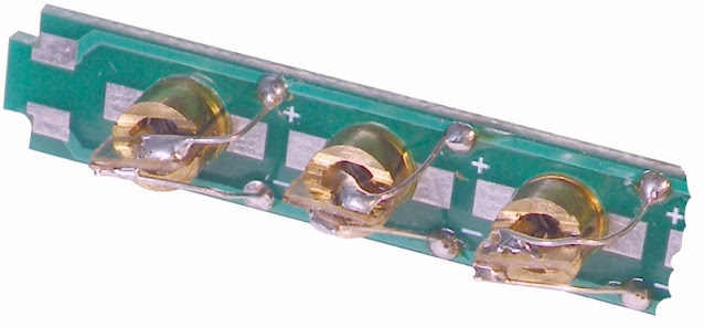
The laser chips are mounted in small copper cylinders with a diameter of 6 mm and are equipped with two soldered thin wires. You can connect these directly to a 5 V DC voltage. According to the official manual, you need to shorten these wires to two centimetres. You mount a laser diode in one of the 6 mm holes on the laser diode board and solder the two wires to the pads with the + and - symbols. That's it!
Because there is some tolerance in the diameters of the diodes and/or the holes in the PCB, not all diodes are fixed firmly in place. The manual advises to fix the diodes with a drop of glue. Do not do this!
The problem is that once you have soldered all the PCBs together you have to align the laser diodes with the LDRs on the base PCB. If you follow the official assembly procedure, this is virtually impossible.
 |
| The prescribed mounting of the laser diodes. (© 2021 Jos Verstraten) |
How did we do it?
We carefully unsoldered the red and black wires from the laser chips, placed the lasers one by one in the holes and used the wires of axial resistors to connect the chips to the PCB. These wires are thick enough to fix the laser diodes firmly in the holes of the PCB. However, these wires are not so tight that you cannot twist or tilt the laser diodes a little when aligning them to the LDRs of the main PCB.
 |
| Our method of mounting the laser diodes. (© 2021 Jos Verstraten) |
Constructing the 'gate'
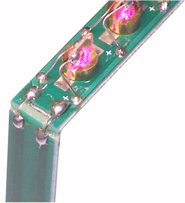
Next, you must connect the laser diode board to the two remaining boards. This must, of course, be done at an angle of 90°. Here, too, we deviated from the prescribed method. We have again used wires from resistors to strengthen the solder joints between the tracks on the narrow PCBs. If you don't, there is a good chance that the copper tracks will tear loose from the PCB's epoxy when you squeeze the construction to fix the three PCBs perpendicularly to each other.
 |
| This is how we attached the three small PCBs to each other. (© 2021 Jos Verstraten) |
Attaching the 'gate' to the main PCB
We attached the two upright narrow PCBs to the base board in the same way: with resistor wires and solder.
Aligning the laser diodes to the LDRs
Connect the laser harp to a 5 Vdc power supply. The seven laser diodes light up immediately and the seven white LEDs light up briefly one by one, first from left to right and then from right to left. This is proof that the circuit works. You should now very carefully twist or tilt the laser diodes until the laser light beams fall precisely centrally on the LDRs of the main PCB.

The final work
You can now connect the loudspeaker and use the two push buttons to listen to the three programmed melodies. If everything works as it should, you can use glue to strengthen the rather fragile connection angles between the four PCBs.
A test of Haodiy's laser harp
The output signal
The oscillogram below shows the shape of the output signal, a perfect symmetrical rectangle with an amplitude of about 4 V.
 |
| The shape of the output signal. (© 2021 Jos Verstraten) |
The frequencies
From left to right the generated frequencies are in the three bands:
- 141 Hz ~ 282 Hz ~ 561 Hz
- 159 Hz ~ 317 Hz ~ 627 Hz
- 178 Hz ~ 355 Hz ~ 704 Hz
- 189 Hz ~ 375 Hz ~ 740 Hz
- 211 Hz ~ 421 Hz ~ 837 Hz
- 237 Hz ~ 473 Hz ~ 937 Hz
- 266 Hz ~ 530 Hz ~ 1,048 Hz
These frequencies are therefore apparently chosen rather arbitrarily, and in any case do not follow the known relationship between the twelve notes in the octaves of each musical instrument. Had this been the case, frequencies of 220 Hz and 440 Hz should have been included in the chosen range.

75 W soldering station

