|
With this low-cost circuit you can experiment with the great power of inductive heating. In less than ten seconds you can heat a massive M8 bolt up to 100 °C. You can also experiment with wireless power transfer (WPT). |
Introduction to the LDTR-WG0222
What is inductive heating?
Before getting to know this device, it might be useful to look at the phenomenon of 'inductive heating'. Inductive heating is a method of heating an electrically conductive object by means of an electric current induced in the object. This technique is a fast, non-contact and flameless way of heating. The heating of the metal is caused by an alternating magnetic field creating 'eddy currents' in the object. These eddy currents are also called 'foucault currents'.
The flow of this current is a consequence of 'electromagnetic induction', a phenomenon discovered by Michael Faraday in 1831. The main fact of Faraday's discovery is that a changing magnetic field can induce a changing voltage in a conductor. This voltage obviously results in a current when the electrical circuit is closed. This is the eddy current that creates very locally generated heat. How deeply the heat penetrates the object depends on the frequency of the magnetic field and the metal. Low frequencies (5 kHz to 30 kHz) penetrate deep into the metal. High frequencies ensure less deep penetration, but stronger heating.
As shown in the figure below, the strong magnetic field is created by making a coil of thick copper wire consisting of just a few windings. This coil has no core, so the coil is hollow.
 |
| The principle of generating an eddy current. (© 2020 Jos Verstraten) |
Don't you believe this is happening so fast? Then buy this inexpensive PCB and find out for yourself!

The LDTR-WG0222 induction heating unit
As is often the case with such cheap Chinese electronic modules, it is unclear who developed the device. You will find this circuit under the name 'LDTR-WG0222', but also under the name 'Geekreit 12V ZVS induction heater'. It is a popular product that is offered by dozens of webshops for quite different prices. If you search long enough you will find on AliExpress vendors that charge less than five euros for it.
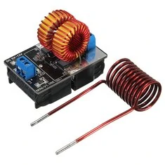
The product looks completely identical at all sellers. The induction heating consists of a small PCB of 55 mm by 37 mm and a separate coil with a diameter of 20 mm and a length of 28 mm. This coil consists of ten windings of solid copper wire. On the left side of the PCB there is a screw terminal block for connecting the power supply, on the right side there is one for connecting the coil. Because the coil cannot possibly fit in that terminal block, you can solder the two connections of the coil directly onto the large tin-plated surfaces, next to the terminal block, on the PCB.
 |
| The PCB and the induction coil. (© eBay) |
All suppliers agree with the minimum technical data given below:
- Supply voltage: 5 Vdc ~ 12 Vdc
- Power output: 120 W max.
- Operating frequency: 200 kHz
The PCB of the LDTR-WG0222
The top layer of the PCB is almost completely occupied by two coils. If you solder these coils out of the PCB, it appears that the circuit contains surprisingly few components. Two MOSFETs, five resistors, four diodes and one LED.
 |
| The top layer of the PCB with and without the coils. (© 2020 Jos Verstraten) |
 |
| The two 330 nF / 630 V capacitors. (© 2020 Jos Verstraten) |
After partially disassembling the PCB in this way, it is not difficult to reconstruct the schematic of this device. In the figure below we have reproduced the complete circuit diagram. The inductors L1 and L2 are the two coils on the PCB. The coil L3 is the separate coil that is responsible for the inductive heating. The two MOSFET's are of the brand ON Semiconductor, but the type number is unreadable.
 |
| The circuit diagram of the LDTR-WG0222. (© 2020 Jos Verstraten) |
We have mentioned the letters 'ZVS' earlier in this article. That is the acronym of 'Zero Voltage Switching' and that is exactly what happens in this circuit when the MOSFETs are in the ON state. This circuit is known as 'Royer oscillator' or 'Mazzilli driver' and guarantees minimal power loss in the circuit itself and maximum power to the external coil.
The circuit is in fact an sine wave oscillator that starts to oscillate at a frequency determined by the load connected between the two drains. In this case, this load consists of the capacitors C1 and C2 and the coil L3. This is called a tank circuit. A parallel connected LC circuit has a resonance frequency. It will not surprise you that the circuit will oscillate at that frequency.
If you suddenly connect the supply voltage to the circuit, the inductors L1 and L2 will ensure that this voltage will reach the drains of the MOSFETs with a slight delay. After all, a coil resists the flow of current.
At the same time, the MOSFETs want to switch to the ON state without delay because positive voltages are applied to the gates through resistors R1 and R2. However, there are no two MOSFETs with identical properties. One of the two will therefore become conductive a little earlier than the other.
Suppose T1 starts conducting a little earlier. The voltage on the drain drops to 0 V and the schottky diode D3 ensures that the voltage on the gate of T2 is pulled to ground. This transistor therefore remains in the OFF state.
The circuit seems to persist in this situation and that would cause the MOSFET T1 to break down. Now however the parallel connected L3-C1-C2 circuit comes into action. When T1 is turned on, a very large current suddenly flows through this semiconductor. This phenomenon causes many high frequency signals in the circuit. The LC circuit extracts the signal with its own resonance frequency from this multitude of frequencies and amplifies it. A fairly high AC voltage is created across this circuit. The negative period of this voltage reaches the gate of T1 via diode D4 and this semiconductor goes to its OFF state. The voltage on the drain rises, with the result that the diode D3 turns off and the gate voltage of T2 can rise. T2 will conduct and T1 will block. The LC circuit coming into resonance causes the transistors to switch status again after half a period. T1 will conduct, T2 will block.
From this statement of operation you can deduce that the MOSFETs are already conducting when there is a minimum voltage on the drains. Hence the name 'Zero Voltage Switching'.
A reaction from Karl Baum
For each circuit the 'right' developer should be named! It is not from the persons mentioned in your blog! This circuit was patented by me in 1985. This was assigned to me in November 1989. Since 2009, (20 years) this circuit is free of claims from my side. With this circuit principle many 10.000 devices (Fa. Hüttinger Elektronik) have been produced with powers from 40 W to 50 kW in medical devices up to applications in the automotive industry.
A large sinusoidal voltage as a result
Thanks to the frequency-selective functioning of the parallel components C1-C2-L3, the circuit generates a sine wave voltage over these components. The frequency of this signal is equal to the resonance frequency of the LC circuit. Due to the energy storage and signal excitation created in LC circuits, this sine wave signal is even many times higher than the power supply voltage of the circuit.
Testing the LDTR-WG0222 induction heating
Important notes
It is absolutely forbidden to power the circuit from a slowly rising supply voltage. The circuit will then not oscillate and both MOSFETs will break down immediately. Make sure that the supply voltage is stable and connect the PCB to the power supply via an ON/OFF switch.
Keep in mind that the circuit can draw up to 7.5 A current from a 12 V power supply and that your power supply must be able to supply such currents without reducing the output voltage. This can cause the oscillator to shut down and destroy the MOSFETs.
Only the sudden appearance of the supply voltage will cause the necessary oscillations in the circuit.
The circuit at rest
We powered our test sample from a 12 V power supply that can supply 30 A. When connecting the PCB to this power supply, a current of 1.35 A is measured at a voltage of 11.55 V. The circuit consumes a power of 15.6 W at rest.
We look at the voltage across L3 on the oscilloscope. Over this part there is indeed a nice sine wave with a frequency of 188.62 kHz, see the oscillogram below. The RMS value of this voltage is 26.158 V.
 |
| The voltage across the coil L3. (© 2020 Jos Verstraten) |
At rest, a considerable amount of power is consumed in the circuit. The parts on the circuit board remain at a pleasant temperature. However, the coil L3 quickly becomes so hot that you burn yourself on it. We were curious to see how hot this coil gets and how quickly it heats up. We measured this by clamping a thermocouple with heat-conducting paste between two windings of the coil and logging the temperature via our multimeter. The results are shown in the graph below. The final temperature is reached after about ten minutes and is 182 °C on our test sample. Indeed a temperature where you can burn yourself considerably!
 |
| The temperature of the coil L3. (© 2020 Jos Verstraten) |
It is noticeable that copper and aluminum objects are not very useful for experimenting with induction heating. This is of course a consequence of the low resistivity of these metals. After all, with copper and aluminum, the heat is generated exclusively through the Joule effect P = I2 ● R. It is better to use iron objects such as nails and bolts to play with the circuit. In ferromagnetic materials such as iron, a lot of extra heat is generated by magnetic hysteresis losses.
To demonstrate the power of inductive heating, we drilled a small hole in which our thermocouple fits in an 80 mm long M8 bolt.
 |
| Heating an M8 bolt, on the left the thermocouple in a hole drilled in the bolt. (© 2020 Jos Verstraten) |
At 600 °C we had to abort our experiment because the heat conducting paste apparently cannot withstand such temperatures and produces a lot of not very healthy smoke.
In any case, this experiment has proven how quickly iron objects heat up with this technique.
 |
| Temperature in the center of the M8 bolt. (© 2020 Jos Verstraten) |
Experimenting with 'Wireless Power Transfer'
'WPT' or 'Wireless Power Transfer' is a current topic. The idea is of course ancient, because even Nikola Tesla was involved in it as early as 1896. All electric toothbrushes charge via this technology and smartphones are also increasingly using wireless charging.
The LDTR-WG0222 is an ideal PCB to experiment with this technique. The magnetic field is of course not only in the core of the coil, but also around the coil. You can pick up this field by holding a coil you make from solid copper wire near L3. You will notice that there is a voltage of several volts across this coil, depending of course on the number of turns and the distance between the coils. The mutual position of the two coils also plays an important role. You can rectify this voltage and provide enough power to light an LED, for example.

Geekreit 12V ZVS induction heater