|
This cheap building kit is a nice entry-level project for people who want to start with electronics as a hobby. For example, you can use it between your turntable and your power amplifier to quickly adjust bass, treble, balance and volume manually. |
Introduction to the LM1036N preamplifier
Setting up your amplifier the old-fashioned way
Most modern digital amplifiers have a volume knob, but no knobs to adjust bass, treble and balance. You have to do this via the remote control and often via an interface on a monitor or TV. Way too complicated! When you are playing vinyl records on your turntable, it is useful to quickly set both the bass and treble controls by hand. A loudness filter that you can quickly switch on or off with a push button is also useful.
This cheap Chinese kit makes this possible, at least if your turntable has a LINE or AUX output. Moreover, it is a nice first introduction to electronics as a hobby. There are no SMD components and all thru-hole parts are therefore easy to solder in the PCB without much experience.
How it should become
In the picture below you can see what the end result of an hour of tinkering looks like. The PCB is only 9.0 cm by 4.5 cm. The result is that the four potentiometers are very close to each other, at a distance of only 2.0 cm. Next to the potentiometers is a push button to switch on the loudness filter. This adjusts the sound at low volume setting to the characteristics of the human ear.
Two RCA chassis jack connectors commonly used for audio are provided as inputs. It is a pity that the output signals are not also available on such connectors, but on a three-pole screw terminal block. That wouldn't have made much difference in price!
On the right are two two-pole screw terminal blocks for connecting the power supply. You can connect a DC voltage of up to 15 V to the upper one. On the lower one you can connect the secondary voltage of a 230V/12V or 230V/15V mains transformer. A rectifier and 12 V stabiliser are present on the board. You have to choose one of the two power supply methods.
 |
| The finished building kit. (© 2020 Jos Verstraten) |
What should it cost?
The prices asked for this kit vary considerably. At AliExpress we found an offer of € 6.90, at HLHV no less than € 23.39 is asked for the same product. So googling pays off!

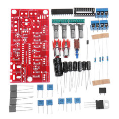
The delivered components
In the picture below, all the components you must solder on the PCB are brought together. The quality is excellent. It is a pity that no buttons for the four potentiometers and the push button are included. We understand that this will cost a little extra, but most hobbyists would appreciate such an extra service.
The printed circuit board
The PCB is of excellent quality. The photo below shows both sides. The print is double-sided, the thru-hole pads are plated and the copper side is provided with a groundplane and of course a soldermask.
The circuit diagram
It is not very difficult to follow the tracks on the PCB and to reconstruct the circuit diagram of this preamplifier. The AC power supply consists of a bridge rectifier type DB107, a pair of capacitors and a stabiliser type LM7812. When supplied with DC, the positive pole is connected to the output of the stabiliser via a diode of type 1N4007. A diode bridges the stabiliser, so that the input of this component does not reach a lower voltage than the output.
The core of the circuit is an LM1036N. This IC, developed a long time ago by NatSemi, contains 2 x 4 voltage controlled stages that control the volume, balance, bass and treble. These control voltages between 0 V and 5.4 V are supplied to the IC by means of four potentiometers powered from pin 17 of the IC.
Strange is that two 380 nF capacitors are drawn on the PCB. That is not a standard value!
Assembling the PCB
Because there is no construction description included and this article is written for the starting hobbyist, we will discuss the assembly of the print point by point.
Start by soldering the four identical resistors, identify them on the PCB with the code '47K'. These are the light blue cylindrical parts with five coloured rings.
Next come the two 1N4007 diodes, black cylindrical parts with one clear white ring. This ring can also be seen on the PCB.
Now solder the bridge rectifier DB107 into the PCB, paying attention to the plus and minus signs on the PCB and on the part.
Solder the 20-pin IC socket into the PCB. It is wise to mount the LM1036N in the socket after this job. This is not so easy and if you wait until the PCB is assembled completely, it will be even more difficult. The problem is that the pins of the IC don't come out of the IC exactly at a 90 degree angle, but are a bit tilted. If you press the pins on one side into the socket, it appears that the pins on the other side do not fit into the contacts of the socket. The only remedy is to bend the two rows of ten pins a bit inwards with a long flat nose pliers until they are really perpendicular out of the IC. Pay attention to the position of the IC!
Did you succeed? Then it is the turn of the polyester capacitors. That's the blue and grey blocks with two wires at the bottom. Between ( ) is the code on the PCB, between [ ] is the code on the part:
- 2 x 10 nF (0.01UF) capacitor [10nK250]
- 4 x 220 nF (0.22UF) capacitor [μ22J63]
- 2 x 470 nF (0.47UF) capacitor [474J100]
- 1 x 100 nF (0.1UF) capacitor [μ10J63]
Next there is the problem that, according to the PCB, you now must solder two 380 nF capacitors which you will not find. That is logical, because that is not a standard value. Supplied are two capacitors of 330 nF [334J100] which you have to solder on the PCB code (0.38UF). Design error on the PCB?
Now you can pay attention to the elcos. These are the black cylindrical parts. They have a white stripe on one side that corresponds to the negative connection. On the PCB you can see this connection in the form of a shaded semi-circle in the elco symbol. The parts are well coded, so there can be no confusion:
- 2 x 4.7 μF (4.7UF)
- 2 x 22 μF (22UF)
- 1 x 47 μF (47UF)
- 1 x 100 μF (100UF)
Once again there is a lack of clarity. On the PCB the last elco is noted as (2200UF/25V). Such a part will not be delivered. However, a similar one of 1,000 μF/25V is supplied. This is a non-critical part, so solder it in place of the 2,200 μF.
The last electronic part you must solder is the voltage stabiliser LM7812. Attention! This is only correct one way and that is with the metal mounting plate facing the 100 μF electrolytic capacitor.
Then solder the push button on the PCB and the four identical potentiometers. First solder these parts with only one of the three pins and neatly align the parts. Then solder the other two pins.
The construction of the circuit ends with the assembly of the two RCA chassis jack connectors and the three PCB screw terminal blocks.
The delivered components
In the picture below, all the components you must solder on the PCB are brought together. The quality is excellent. It is a pity that no buttons for the four potentiometers and the push button are included. We understand that this will cost a little extra, but most hobbyists would appreciate such an extra service.
 |
| All the components of this kit. (© 2020 Jos Verstraten) |
The printed circuit board
The PCB is of excellent quality. The photo below shows both sides. The print is double-sided, the thru-hole pads are plated and the copper side is provided with a groundplane and of course a soldermask.
 |
| The two sides of the PCB. (© 2020 Jos Verstraten) |
The circuit diagram
It is not very difficult to follow the tracks on the PCB and to reconstruct the circuit diagram of this preamplifier. The AC power supply consists of a bridge rectifier type DB107, a pair of capacitors and a stabiliser type LM7812. When supplied with DC, the positive pole is connected to the output of the stabiliser via a diode of type 1N4007. A diode bridges the stabiliser, so that the input of this component does not reach a lower voltage than the output.
The core of the circuit is an LM1036N. This IC, developed a long time ago by NatSemi, contains 2 x 4 voltage controlled stages that control the volume, balance, bass and treble. These control voltages between 0 V and 5.4 V are supplied to the IC by means of four potentiometers powered from pin 17 of the IC.
Strange is that two 380 nF capacitors are drawn on the PCB. That is not a standard value!
 |
| The complete circuit diagram. (© 2020 Jos Verstraten) |
Building the preamplifier
Assembling the PCB
Because there is no construction description included and this article is written for the starting hobbyist, we will discuss the assembly of the print point by point.
Start by soldering the four identical resistors, identify them on the PCB with the code '47K'. These are the light blue cylindrical parts with five coloured rings.
Next come the two 1N4007 diodes, black cylindrical parts with one clear white ring. This ring can also be seen on the PCB.
Now solder the bridge rectifier DB107 into the PCB, paying attention to the plus and minus signs on the PCB and on the part.
Solder the 20-pin IC socket into the PCB. It is wise to mount the LM1036N in the socket after this job. This is not so easy and if you wait until the PCB is assembled completely, it will be even more difficult. The problem is that the pins of the IC don't come out of the IC exactly at a 90 degree angle, but are a bit tilted. If you press the pins on one side into the socket, it appears that the pins on the other side do not fit into the contacts of the socket. The only remedy is to bend the two rows of ten pins a bit inwards with a long flat nose pliers until they are really perpendicular out of the IC. Pay attention to the position of the IC!
Did you succeed? Then it is the turn of the polyester capacitors. That's the blue and grey blocks with two wires at the bottom. Between ( ) is the code on the PCB, between [ ] is the code on the part:
- 2 x 10 nF (0.01UF) capacitor [10nK250]
- 4 x 220 nF (0.22UF) capacitor [μ22J63]
- 2 x 470 nF (0.47UF) capacitor [474J100]
- 1 x 100 nF (0.1UF) capacitor [μ10J63]
Next there is the problem that, according to the PCB, you now must solder two 380 nF capacitors which you will not find. That is logical, because that is not a standard value. Supplied are two capacitors of 330 nF [334J100] which you have to solder on the PCB code (0.38UF). Design error on the PCB?
Now you can pay attention to the elcos. These are the black cylindrical parts. They have a white stripe on one side that corresponds to the negative connection. On the PCB you can see this connection in the form of a shaded semi-circle in the elco symbol. The parts are well coded, so there can be no confusion:
- 2 x 4.7 μF (4.7UF)
- 2 x 22 μF (22UF)
- 1 x 47 μF (47UF)
- 1 x 100 μF (100UF)
Once again there is a lack of clarity. On the PCB the last elco is noted as (2200UF/25V). Such a part will not be delivered. However, a similar one of 1,000 μF/25V is supplied. This is a non-critical part, so solder it in place of the 2,200 μF.
The last electronic part you must solder is the voltage stabiliser LM7812. Attention! This is only correct one way and that is with the metal mounting plate facing the 100 μF electrolytic capacitor.
Then solder the push button on the PCB and the four identical potentiometers. First solder these parts with only one of the three pins and neatly align the parts. Then solder the other two pins.
The construction of the circuit ends with the assembly of the two RCA chassis jack connectors and the three PCB screw terminal blocks.
 |
| The fully assembled PCB. (© Banggood) |
Connecting the PCB
You can connect the two RCA chassis jack connectors with two shielded cables with RCA connectors to the LINE or AUX outputs of a music producing device. Even if you connect the PCB to a turntable, you must have a turntable with such an output!
To connect the outputs you buy a third shielded cable with RCA connectors. You cut these into two equally long pieces. The ends without connectors must be stripped off and connected to the PCB according to the assembly drawing below. The shields of both cables must be screwed into the middle contact of the screw terminal block.
Buy a 12 V / 100 mA transformer and connect its 12 V solder tags to the 'AC12V' screw terminal block on the PCB. Connect a mains cable to the 230 V solder tags of the transformer. You can also buy a stabilised mains power supply that supplies 12 VDC. However, you will need to cut the connector of the cable and connect the two cores of the cable, after stripping, to the + and - of the upper scres terminal block. Because the polarity of such cables is not standardised, you first need to measure with your multimeter on which conductor the plus and on which conductor the min is. It is a pity that a standard 5.5 mm x 2.1 mm chassis jack connector has not been integrated on the PCB for this purpose!
 |
| Wiring the PCB. (© 2020 Jos Verstraten) |
Testing the LM1036N preamplifier
The power consumption
We powered the preamplifier from 15 VDC, a current of 30 mA was drawn.
The amplification of the circuit
According to the specifications, the circuit amplifies the input signal between -2 dB and +2 dB at 1 kHz and the volume potentiometer in its maximum position. Under these conditions, an amplification of 1.2 dB was measured on the specimen we built.
The noise of the circuit
With open inputs, tone controls in the middle position and maximum volume, the noise voltage on the two outputs was measured: 0.41 mV left and 0.53 mV right.
Maximum input voltage before clipping
This was measured with a sine signal of 1 kHz on both inputs, tone controls in the middle and maximum volume. The maximum permissible input voltage is 1.1 V.
Square wave testing
In the picture below you see, from left to right, the testing of square wave signals of 100 Hz, 1 kHz and 10 kHz. Of course the tone controls are set to the neutral middle position. The yellow traces are the input signals, the blue the output signals. Remarkable is that the circuit causes a phase shift of 180° between the input and the output signals.
 |
| Processing of square wave signals of 100 Hz, 1 kHz and 10 kHz. (© 2020 Jos Verstraten) |
Harmonic distortion
The distortion was measured with a sine wave input signal of 300 mV, with maximum volume and with neutral tone controls:
- 100 Hz: 0.15 %
- 1 kHz: 0.11 %
- 10 kHz: 0.16 %
As the oscillogram below shows, the distortion is almost entirely due to the second harmonic of the input signal. The yellow signal is the output signal of the circuit, the blue signal is the distortion filtered out. The datasheet of the LM1036N gives a typical distortion of 0.06 % for a signal of 300 mV and 1 kHz, but the maximum value can be as high as 0.3 %.
 |
| The harmonic distortion at 1 kHz and 300 mV input signal. (© 2020 Jos Verstraten) |
The frequency response in the neutral position
With the two potentiometers for the tone control in the middle position, we measured the passband of the circuit. This was almost straight from 20 Hz to 20 kHz. At 10 Hz an attenuation of -1.0 dB was measured, around 100 Hz a small gain of up to +0.2 dB was detected.
 |
| The frequency response is in the neutral position. (© 2020 Jos Verstraten) |
The frequency response at minimum and maximum tone control
The same characteristic, now measured at minimum (green) and maximum (red) tone control settings, is shown below. The graph largely complies with the well-known Baxandall curve, which has become the standard for bass and treble controls. The circuit providing this frequency response was described in Wireless World as early as 1953 by the English engineer Peter J. Baxandall.
 |
| The frequency response at maximum and minimum tone control. (© 2020 Jos Verstraten) |
The loudness filter
Such a filter adjusts the frequency response of an amplifier to the hearing curve of the human ear. This is not identical for all loudnesses. Music that sounds powerful at high volume, sounds limp and lifeless at low volume. To compensate for this phenomenon, you can increase the amplification of low and high frequencies by pressing the loudness switch. Of course we have tested this too, with the volume potentiometer set in the middle of the range. The results are shown in the graph below.
 |
| The frequency response with the loudness filter enabled. (© 2020 Jos Verstraten) |
Our opinion on this building kit
The quality of the parts is excellent and the PCB is easy to solder. The measured specifications meet the values published by the manufacturer. The only thing we find unfortunate is that the outputs are equipped with a screw terminal block and not with two RCA chassis jack connectors and that the DC power connection is not equipped with a standard power chassis jack. That would have made the use of the PCB much easier. And of course the buttons for the push button switch and the four potentiometers should not have been missing either.

LM1036 Luxurious Preamplifier Volume Control Tone Board