|
Maglev stands for 'magnetic levitation', the use of magnetic fields to make metal objects float. With this kit, you can demonstrate this principle and gain experience with it. However, we were unable to get this kit to work! |
Introduction to this building kit
Manufacturer, suppliers, prices
According to a bad Chinese custom, it is completely unclear by whom this kit is manufactured. It turns out that, again a bad Chinese custom, there are various versions that are all for sale under the same name. If you google 'magnetic levitation kit 300g', you will see the various versions appear on your screen. We have bought the expensive version, which goes through life with the addition '300g'. This means that this model is capable of levitating an object with a maximum weight of 300 grams. This model is characterized by the eight permanent magnets that are present on the top PCB. This model can be purchased, for example, at Banggood and via AliExpress for a price of approximately € 38.00. We ordered our copy from Banggood, see the sponsor ad at the end of this article. There are also slightly more expensive versions on the market where there are a number of blue LEDs on the edge of the print are included, which give the product the blue appearance that many consider to be 'magical'.
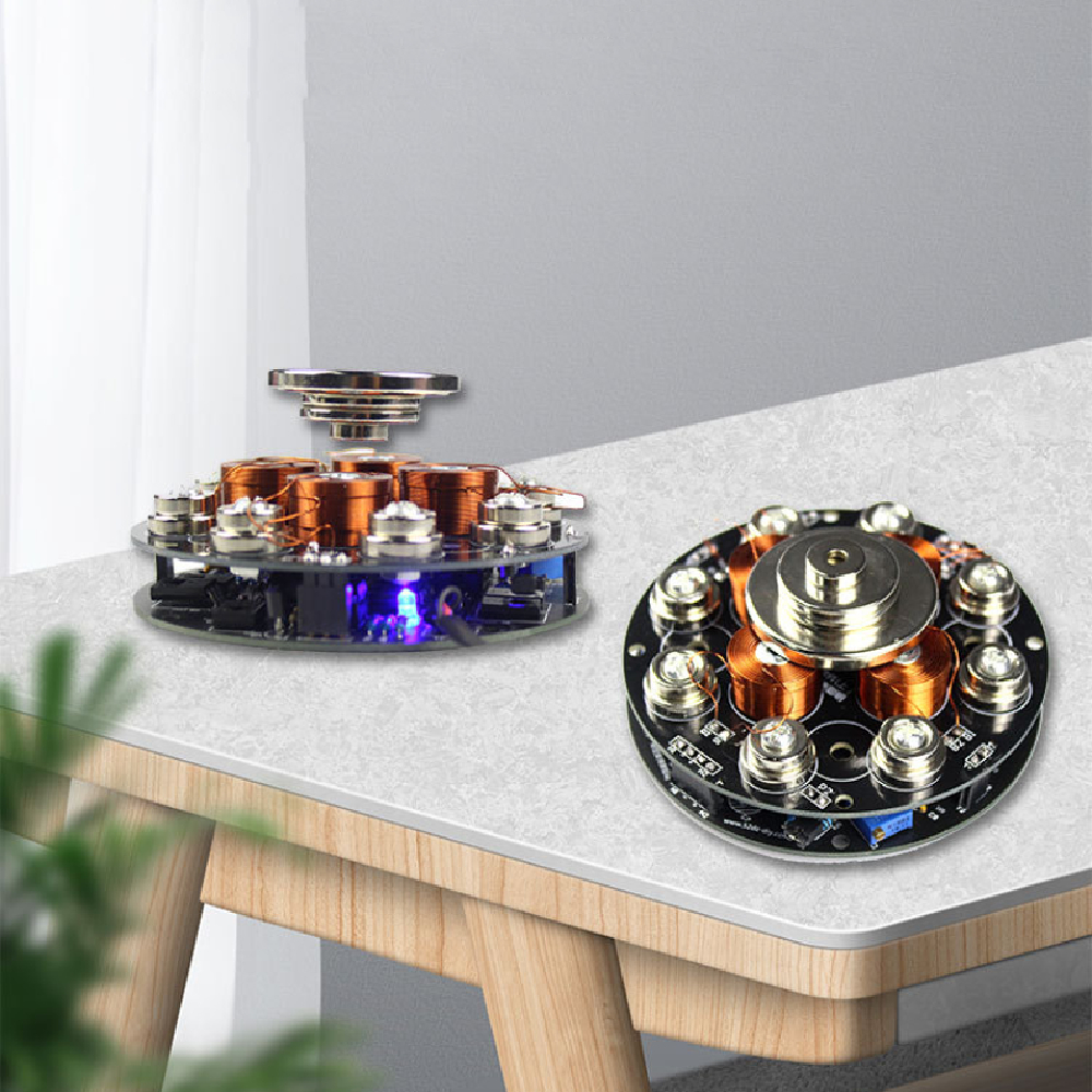
The end result of this kit
In the photo below you can see what you can expect after a few hours of not too difficult tinkering, but nerve-racking adjustments. A strange device, built on two round PCBs with a diameter of 90 mm and a total weight of 250 grams. You need to power the device from a DC voltage of 12 V, taking into account a maximum current of about 1.5 A.
 |
| The fully assembled kit. (© Banggood) |
How it works
Also supplied are four disc-shaped very strong magnets, which form the 'platform' on which you can make things float. After adjusting the device, you must hold one or more of these discs above the top PCB. That magnet is attracted by the eight permanent magnets that are present on this PCB. Of course, those eight magnets do not have exactly the same attraction forces. Without something extra, the round magnet is attracted a little more to one of the eight, flies in that direction with considerable force and sticks to the magnet.
That 'extra' are four coils that are also present on the top PCB. Between these four coils are three hall sensors, which can measure the strength of the magnetic field in one direction and convert it into a DC voltage. Those three DC voltages control the electronics of this maglev demo kit. The result is that direct currents are sent through the four coils. These currents cause additional magnetic fields around the coils. These opposing fields ensure that the whole remains magnetically balanced and that the round magnetic disk floats quietly about 2.5 cm above the device. Impressive to see! You can put small, light objects on the disc without any problems. The three hall sensors immediately notice that the balance is broken and the electronics send more or less current through the four coils until the balance is restored. The video clip below, taken from a YouTube video by Titanes, shows how this maglev demo kit works.
The delivered parts
The photo below shows all the parts that are included in the kit. The quality is excellent, but unfortunately the same cannot be written about the packaging. The electronic parts are crammed together in a plastic bag that is far too small, with the result that we got ICs with rather bent pins. Another very bad Chinese habit! Fortunately not so bad that they could not be straightened, but such a thing is not allowed and is easily prevented.
The two PCBs are double-sided with plated through holes and provided with component silkscreen and solder mask. The package comes standard with a mains plug supply that supplies 12 Vdc and a maximum of 2 A, unfortunately with an American mains plug.
 |
| All the supplied parts. (© 2022 Jos Verstraten) |
No building description!
Again, according to a bad Chinese custom, this kit is supplied without a building description. This is manageable for some construction kits because the builder can successfully complete the construction on the basis of the component silkscreen on the PCB. With this kit, however, this is unforgivable because there are two adjustment potentiometers on the PCB and you do not know how to adjust them without a good manual.
After some research on the internet we were able to find two building descriptions, a short one in English and a much more extensive one in Chinese. The latter is about a slightly different version of the maglev kit, but can be used as documentation. As is our custom, we have saved these two PDFs in our cloud on Google Drive, so you can view and download both with one click:
➡ Maglev_Demo_Kit_Manual_English.pdf
➡ Maglev_Demo_Kit_Manual_Chinese.pdf
The Chinese text is easy to translate with Google Translate. Select the text with the mouse and copy it to the Google Translate window. You will receive an understandable Dutch or English translation.
The electronics in the maglev demo kit 300g
Introduction
Because there are various slightly different versions of this kit in circulation, little exact information can be found about the circuits used. So what is described in this section may not fully apply to the version you have purchased.
The power supply
A stable 5 V, which is used to supply part of the electronics, is made from the 12 V of the power supply by means of a 78L05. In addition, a TL431 temperature-compensated adjustable zener diode is present. This is probably used to power the three hall sensors.
The control system
The figure below shows how the control system works with the three hall sensors SEN-X, SEN-Y and SEN-Z as input and the four coils Lx1, Lx2, Ly1 and Ly2 as output. The two coils in the x-direction Lx1 and Lx2 are in series, as are the two coils Ly1 and Ly2 in the y-direction. Jumpers J1 and J2 are located between the two coils. This is important when adjusting the device. The coils are driven from bridge circuits composed of four transistors and two operational amplifiers. Those bridge circuits are in turn controlled from differential amplifiers IC3 and IC4. These compare the sensor voltages SEN-X and SEN-Y with trimming voltages that are set with the two ten-turn adjustment potentiometers Rtrim.
 |
| The principle of operation of the control system. (© 2022 Jos Verstraten) |
The output stages that deliver the current to the coils are not supplied from +12 V, but from a voltage +Ur. That voltage is generated by the circuit around IC7 and IC8. The third hall sensor SEN-Z is perpendicular to the other two and detects the presence of the disk-shaped magnet above the coils. If it is not present, the transistor T9 is cut off and there is no +Ur. The output stages are not powered and the coils are de-energized. If you hold the disc-shaped magnet above the coils, you will notice that at a certain distance the LED lights up. At that time, the sensor SEN-Z has detected the presence of the magnet and the transistor T9 is driven into saturation. The +12 V is connected to +Ur and the coils are supplied with power. The control system works (or should work, read on)!
Building the maglev demo kit 300g
Soldering the control board
The component side of the control board is shown in the figure below. You can print this photo and use it to mark off the soldered parts.
 |
| The bare control PCB. (© 2022 Jos Verstraten) |
The best soldering order is:
- The 8 1N4148 diodes, note the cathode stripe on the housing of the diode.
- The 31 resistors.
- The 4 transistors B882, you have to bend the connecting wires 90° with a pair of pliers.
- The 5 transistors B772, idem.
- The 2 ICs of type LM324.
- The IC of type LM393.
- The TIL431 and the 78L05.
- The 2 capacitors 104 and the two capacitors 105.
- The 2 adjustment potentiometers of 10 kΩ, you have to bend the connecting wires 90° with a pair of pliers.
- The LED, the shortest wire is the cathode.
- The 4 electrolytic capacitors, note the polarity.
- The 4 female PCB connectors with 1 x 5, 1 x 4 and 2 x 2 contacts.
- The power connector.
- The 4 brass spacers on the other side of the PCB.
 |
| The completely soldered control board. (© 2022 Jos Verstraten) |
The PCB with the magnets
Mounting the second PCB is a little more complicated. Start by assembling two of the four coils. Make sure you screw them on with the connection wires pointing upwards. Do this with the necessary caution, because the thin winding wires are quite fragile and if you go a bit wild, one will break. That happened to us, but luckily we were able to repair the broken wire.
Then solder the three hall sensors of type 503-918 on the PCB so that the parts are at half the height of the coils. The wires of one of the three sensors must first be bent 90° with the label on the sensor facing up. This mounting step is explained in the photo below. Solder the sensors with the utmost accuracy! The two sensors SEN-X and SEN-Y must be really perpendicular to the PCB and really at an angle of 90° to each other.
 |
| The mounting of the three hall sensors. (© 2022 Jos Verstraten) |
Mount the two remaining coils. Solder the wires coming out of the core of the coils into pads A1, B1, C1 and D1. Solder the wires coming out of the outside into pads A2, B2, C2 and D2.
Screw the eight permanent magnets onto the PCB. Mount the four male PCB connectors (1 x 5, 1 x 4, 2 x 2 contacts) with the long pins on the other side of the PCB and solder the short pins on the side where the parts are located. Finally, solder the two right-angled PCB connectors (2 x 2 contacts) to the PCB, it does not matter on which side.
On the edge of the print, in front of the magnets, there are 2 x 8 pads that are still free. With some kits, eight blue SMD-LEDs have to be soldered to this, which illuminate the device. However, these LEDs are not present in the version ordered by us.
 |
| The completely mounted magnets PCB. (© 2022 Jos Verstraten) |
Adjusting the Maglev demo kit 300g
The first activities
Assemble the two PCBs by pushing the four male connectors on the magnet PCB into the four female connectors on the control PCB. Bridge one of the right-angled PCB connectors with the supplied jumper. Connect a DC ammeter to the two pins of the second right-angled connector, switched to the 1 A range. If you still have an old-fashioned analog multimeter, you can use it for this, because you have to adjust the current to the minimum value the current must be adjusted to the minimum value and this is best done with a needle meter.
Connect the device to a well-stabilized DC voltage of 12 V. If everything goes as it should, the ammeter will indicate a maximum of twenty mA.
 |
| Measuring the current through the magnets. (© 2022 Jos Verstraten) |
Adjusting the magnetic fields
It is now the intention that with one hand you hold the disc-shaped magnet at a distance of about 2.5 cm above the four coils and that as centrally as possible. The current rises to about 0.5 A. With the other hand you have to adjust the relevant trimming potentiometer with a screwdriver so that the current absorbed by the coils is minimal. Afterwards you must repeat this procedure for the other coils. So: move the jumper from the first right-angled PCB connector to the second and move the ammeter from the second to the first connector. Afterwards you have to hold the magnet again in the same position above the coils and adjust the second potentiometer to minimum current.
It is now the intention that with one hand you hold the disc-shaped magnet at a distance of about 2.5 cm above the four coils and that as centrally as possible. The current rises to about 0.5 A. With the other hand you have to adjust the relevant trimming potentiometer with a screwdriver so that the current absorbed by the coils is minimal. Afterwards you must repeat this procedure for the other coils. So: move the jumper from the first right-angled PCB connector to the second and move the ammeter from the second to the first connector. Afterwards you have to hold the magnet again in the same position above the coils and adjust the second potentiometer to minimum current.

That's how it is described, but at least it didn't work for us. After many failed attempts, we devised an auxiliary construction to keep the magnet in a fixed position above the coils. With a hole saw, we sawed a circle out of a 2.5 cm thick piece of MDF on which we glue the magnet. In this way it is possible to fix the magnet above the coils in an identical manner for both adjustments and the adjustment is much smoother.
Bending the hall sensors
Even after repeating this procedure several times, we were unable to get the system stable. The disk magnet did not float stably and landed on one of the eight permanent magnets.
Including two ammeters in both output circuits, so that both potentiometers could be adjusted to minimum current at once, did not help either.
On the advice of the internet, we bent the hall sensors a bit to better position them. However.... all this had no result!
Our conclusion about this kit
There are plenty of photos and videos on the internet of people who have successfully build this kit and apparently had no trouble adjusting it at all. Just watch the video at the beginning of this article! However, we have not yet succeeded in floating the disc-shaped magnet in a stable position above the coils. The magnet always landed on one of the eight permanent magnets with a bang.
Careful inspection of the construction, of the installed components and of our soldering could reveal no fault. Unfortunately, after hours of experimenting with the adjustment, we have let this project rest. We are curious if there are readers who dare to take up this challenge and see a floating magnet on their workbench as a reward. Keep us informed about your experiences!

Maglev demo kit