Introduction to the MAX038 function generator kit
The ready-to-use device
To give you an impression of what you can expect from this kit, we show you the final result in the picture below. If you do not like the brown color of the housing, you can remove this paper layer from the transparent plexiglass and you will also see the PCB of your measuring device. Unfortunately, the lettering of the front panel is no longer present, because it is not etched into the plexiglass.
The 8.8 cm by 4.9 cm PCB must be mounted in the 9.9 cm by 5.9 cm by 3.2 cm plexiglass housing.
On the left is a standard 5.5 mm x 2.1 mm power supply socket for the supply voltage of 9.0 Vdc to 15.0 Vdc. On the right there is a quadruple screw terminal block with the ground, the sync output and two signal outputs. One output provides the output signal that the MAX038 provides, the second output delivers a signal that can be adjusted in amplitude and offset. The sync output is also directly connected to the SYNC pin of the MAX038.
With the yellow pushbutton, you can set the shape of the output signal to sine, triangle or square. A green jumper allows you to set the frequency range in eight ranges between 1.0 Hz and 20 MHz. With a second green jumper you can choose between a fixed duty-cycle of 50 % and an adjustable duty-cycle. With the four potentiometers you control, from left to right, the duty-cycle, the frequency, the offset and the amplitude.
 |
| The ready-to-use device. (© 2020 Jos Verstraten) |
The technical specifications
According to the supplier, this circuit has the following specifications:
- Power supply: 9.0 Vdc ~ 15.0 Vdc
- Internal supply voltages: ±5.0 Vdc
- Signal shapes: sine, triangle, rectangle, sawtooth
- Frequency range: 1 Hz ~ 20 MHz
- Temperature drift: 200 ppm/°C
- Duty-cycle: 15 % ~ 85 %
- Sine distortion: 0,75 % typical
- Linearity triangle: 0,1 % typical
- Output voltage: 9.5 Vpeak-to-peak max.
- Offset: ±5.0 V max.
It will be clear that the specification 'sawtooth' must be taken with a grain of salt. If the duty-cycle is adjustable to only 85 %, there can be no question of the generation of a nice sawtooth with a steep trailing edge.
The delivery of the package
As with most Chinese kits, little attention is paid to packaging upon delivery. In this case, all electronic parts are packed in one plastic bag and the housing parts in a second. As a result, the 20-pin IC socket of our kit was irreparably damaged. One sheet of paper is included that should represent the building description. On that sheet of paper is a small drawing of the component arrangement plus a table with all the parts. For some mysterious reason, some Chinese text is printed over this table, so that some rows of the table are partially illegible. A more detailed building description can be found at:
http://www.mcustudio.com.cn/zl/max038/max038__.html
 |
| The delivery of this kit. (© 2020 Jos Verstraten) |
The electronics of this MAX038 kit
The circuit around the MAX038
The schematic below shows the part of the circuit around the MAX038. To select the waveform, push button S1 is used. It controls one of the inputs of the programmed microcontroller MCU1103 (U2). Two outputs of this IC go directly to the A0 and A1 inputs of the MAX038. The code combination on these two pins determines whether the generator generates a sine, triangular or rectangular signal.
The MAX038 (U5) is powered between +5 V and -5 V. Both voltages are decoupled at the IC with capacitors C2 and C3. A total of nine pins go to ground.
The frequency range is set by means of the PCB header P1. You can put the 2.54 mm jumper in one of the eight positions:
- 2 MHz ~ 20 MHz
- 300 kHz ~ 2 MHz
- 70 kHz ~ 300 kHz
- 7 kHz ~ 70 kHz
- 700 Hz ~ 7 kHz
- 75 Hz ~ 700 Hz
- 6 Hz ~ 75 Hz
- 1 Hz ~ 6 Hz
These are rather strange ranges, but of course that has everything to do with the values of the capacitors C15 to C21 that define these frequency ranges. The fine tuning of the frequency is done with the potentiometer R9, which supplies an adjustable current to the IIN pin of the MAX038. With the PCB header W5 you can choose whether you want a time-symmetrical output voltage or one of which you can set the duty-cycle. In the latter case, you can adjust this parameter using the potentiometer R10. Both potentiometers are powered from the voltage reference present on pin 1 of the MAX038. This voltage is decoupled with capacitor C7. The sync output on pin 14 is directly connected to the PCB terminal H2. The signal output on pin 19 is connected to the input of the amplitude and offset control.
 |
| The circuit around the MAX038. (© 2020 Jos Verstraten) |
The amplitude and offset control
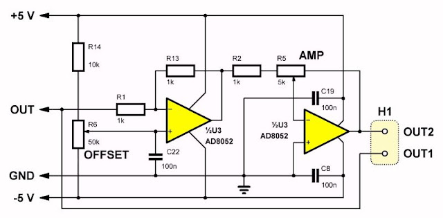
This circuit, shown in the figure below, uses a double op-amp type AD8052 (U3). This is a wideband op-amp with a unity-gain bandwidth of 110 MHz (-3 dB) and a slew rate of 145 V/μs. In addition, the circuit is capable of delivering 45 mA current from the output. In short, an ideal circuit as an output stage for such a wideband function generator!
In the first stage, you can set the offset to the output voltage with the potentiometer R6. This stage is a standard inverting amplifier with a voltage gain of -1. The offset is obtained by applying an adjustable DC voltage to the non-inverting input of the op-amp. The capacitor C22 provides an extra decoupling of this voltage.

In the second stage, the signal is amplified. This is also an inverting amplifier, you can adjust the gain by means of the potentiometer R5. When the slider is in the right position, the inverting input is directly connected to the output of the op-amp. Because the non-inverting input is grounded, the voltage at the inverting input and thus at the output will also go to ground. After all, an op-amp always maintains voltage equality at both inputs. When the slider is in the left position, the voltage gain of the circuit is maximal.
The OUT pin of the MAX038 is connected to the OUT1 output on the screw terminal H1, the output of the op-amp to OUT2.
 |
| The amplitude and offset control. (© 2020 Jos Verstraten) |
The power supply of the circuit
The output voltage of the mains plug power supply, a voltage between 9.0 Vdc and 15.0 Vdc, is converted into two symmetrical supply voltages of ±5 V via the circuit below. The external supply voltage, which is supplied via JK1, first goes to a 78M05 stabiliser (U1) which turns it into +5 V. From this voltage a negative voltage of -5 V is generated by means of an ICL7660 (U4).
 |
| The power supply of the function generator. (© 2020 Jos Verstraten) |
Building the MAX038 function generator
The printed circuit board
In the picture below, the two sides of the PCB are shown. The solder pads are extremely small, so it is important to use a soldering tip with a very small point. We have marked the location of the six SMD components in red.
 |
| The two sides of the PCB. (© 2020 Jos Verstraten) |
The components
The components to be soldered and mounted on the PCB are shown in the figure below. The MAX038 is delivered with socket.
 |
| These components must be soldered and mounted on the PCB. (© 2020 Jos Verstraten) |
First step: soldering of C13 and C21
These two components are capacitors of 47 μF in sub-miniature 0805 SMD housing. This means that these parts are only 1.25 mm by 2.00 mm! It is quite a challenge to solder these parts on the PCB. If you can't do that, it's not a disaster. After all, these two capacitors only determine the lowest frequency range from 1 Hz to 6 Hz, which you hardly ever need in daily practice.
 |
| Dimensions and packaging of the two 0805 capacitors. (© 2020 Jos Verstraten) |
Second step: soldering the SMD ICs on the PCB
The 5 V stabilizer and three ICs are also supplied as SMDs, which you need to solder to the PCB as a second step. The chips have at the top left of pin 1 a small circle that is slightly recessed in the housing and that is shown a bit exaggerated in the picture below. This picture shows you how to mount the chip over the silkscreen symbol on the PCB. Apply a very small amount of soldering tin to one of the pads in a corner. Then position the chip in the right place while keeping the soldering tin liquid. A pair of tweezers is essential for this. It is important that you place the component correctly on the pads, otherwise the other pads cannot be soldered properly. Then solder the other pads. Inspect the connections with a magnifying glass and remove the soldering flux with isopropanol alcohol if necessary. This does not necessarily have to be done, but gives a more finished result. If there is too much solder on a pad, it can easily be removed with a piece of desoldering braid.
 |
| Soldering the SMD chips. (© 2020 Jos Verstraten) |
Third step: assembling the other components
Compared to soldering the SMD components, mounting the other components on the PCB is child's play. Start with the resistors and then the brown capacitors. Before soldering, as an extra check, measure the value of the component with your multimeter. What struck us was that the supplied capacitors have a very large tolerance. Deviations of more than 30% were measured. If you consider that these capacitors are responsible for the various frequency ranges, it is already clear that there will be large tolerances on the specified ranges.
Then solder the two electrolytics, pay attention to the plus and the minus! By soldering the IC socket for the MAX038, the three PCB headers, the two PCB screw terminals, the power connector, the pushbutton and the four potentiometers, you end the soldering to the PCB. You can see the result on the picture below.
 |
| The completely assembled PCB. (© 2020 Jos Verstraten) |
The housing consists, as is often the case with such cheap Chinese kits, of six sheets of plexiglass with a brown paper coating on both sides. You can remove these or decide to leave them in place. The four small bolts and nuts have to be mounted in the four 3 mm holes in the corners of the PCB. You can then click the PCB with these bolts into the bottom panel of the enclosure, click the four side panels into the bottom panel and finally click the front panel into the four side panels. Use the four self-tapping screws to join the six panels together to form a stable housing. Attach the four buttons to the axes of the potentiometers and your function generator is ready to use.
 |
| The parts of the housing. (© 2020 Jos Verstraten) |
Testing the MAX038 function generator
Test conditions
We powered the specimen to be tested from a 12 Vdc mains power supply. The two internally generated supply voltages are +4.859 V and -4.475 V for our specimen. All measurements were performed with a resistive load of 50 Ω on the output and with a 1/1 oscilloscope probe connected to an oscilloscope with a bandwidth of 100 MHz. We have performed most of the measurements on the upper output, the ones that are controlled by the potentiometers of the offset and the amplitude.
The frequency ranges
These were measured on the sync output because this output generates the best signal for frequency measurements. The first observation is that the upper 10% of the setting of the potentiometer is unusable because then strange signals are generated. The measurement was performed with the DUTY jumper in the '50%' position. The results are summarized in the table below.
The frequency ranges are determined by the value of the capacitors connected to pin 5 of the MAX038. We already wrote that we found large tolerances on the value of these capacitors. So it is not surprising that the measured eight frequency ranges are quite different from what the specifications predict.
 |
| The measured frequency ranges. (© 2020 Jos Verstraten) |
The second negative experience when working with this function generator is that the range of the offset is far too large. With a large output signal, this signal crashes against the supply voltage or the ground level if you turn the offset potentiometer a little too much. This of course has everything to do with the low supply voltages of ±5.0 V. These are the maximum voltages the MAX038 can be powered with. With a better (and more expensive) design, you need to work with two sets of supply voltages. One of ±15 V to supply the output amplifier and one of ±5.0 V to supply the MAX038.
With both potentiometers adjusted to the best setting, the circuit delivers a sine wave of up to 2.2 Vrms. This is less than the specified 3.35 Vrms (9.5 Vpeak-to-peak), but enough for most applications.

The output signals at 1 kHz
This and subsequent measurements are performed with the potentiometers of offset and amplitude in such a position that the generator produces a nice symmetrical sine wave of 1 Vrms. The three signal shapes are, as can be expected, excellent and not even worth a picture.
The output signals at 100 kHz
Much more interesting are the waveforms at this frequency! Even at this already quite high frequency, the output signals are excellent, see the picture below.
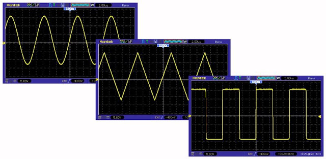 |
| The output signals at 100 kHz. (© 2020 Jos Verstraten) |
Same measurements, but now at 1 MHz. On our AC millivoltmeter PM2454 we see that the RMS value of the sine wave is still exactly 1 V.
 |
| The output signals at 1 MHz. (© 2020 Jos Verstraten) |
After 1 kHz, 100 kHz and 1 MHz it is logical to test at 10 MHz. That makes little sense, because at this frequency the three signals resemble each other like three drops of water. Apparently, the bandwidth of the circuit is too low to amplify the higher harmonics of a 10 MHz signal. At 5 MHz, however, the generator still delivers three signals that are clearly distinguishable as such, see the figure below.
The two horizontal dotted cursor lines indicate the peak-to-peak value of the sine signal at 100 kHz. This clearly shows that the generator has a very flat frequency response up to 5 MHz.
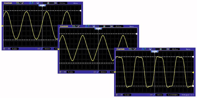 |
| The output signals at 5 MHz. (© 2020 Jos Verstraten) |
The function generator, set to the highest frequency of 14 MHz, produces a good usable sine wave, see the picture below. The two other signals deform at this frequency to a sine.
 |
| The sine wave at 14 MHz. (© 2020 Jos Verstraten) |
In addition to the maximum voltage generated by a function generator, the minimum voltage is also very interesting. After all, if you are experimenting with audio circuits, a voltage of 2.0 V will not help you much, but a voltage of 100 mV will be all the more useful. For stable adjustment of such small voltages, you should actually have a professional generator that not only has an amplitude potentiometer, but also a calibrated step attenuator. However, you can get a fairly clean sine wave with an RMS value of 100 mV out of this device without much effort, see the picture below.
 |
| The sine wave at 100 mVrms. (© 2020 Jos Verstraten) |
According to the specifications, the generator would have an adjustable duty-cycle from 15% to 85%. So put the green jumper in the left position and try it out! Starting point was a symmetrical square wave with a frequency of 100 kHz. When varying the duty-cycle, the frequency deviated slightly:
- duty-cycle 15%: 96.04 kHz
- duty-cycle 85%: 96.32 kHz
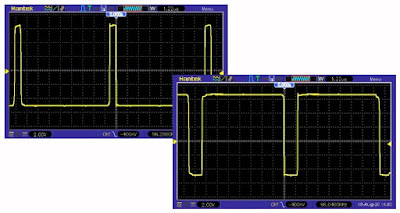 |
| The range of the duty-cycle potentiometer. (© 2020 Jos Verstraten) |
According to the specifications, the generator delivers a sine wave with a maximum harmonic distortion of only 0.75% typical. Quite unbelievable! Because this parameter is in fact only important when measuring audio equipment, we have measured the distortion in the range of 20 Hz to 20 kHz at an output voltage of 1 Vrms. The disappointing results are summarized in the table below.
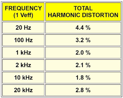 |
| The harmonic distortion in the audio range. (© 2020 Jos Verstraten) |
 |
| The harmonic distortion on a 1 V and 1 kHz sine wave. (© 2020 Jos Verstraten) |
Our opinion about this MAX038 function generator kit
It is clear that this kit does not meet the specifications guaranteed by the manufacturer on several points. No 20 MHz as the maximum frequency, no 0.75 % distortion on the sine wave, no 3.35 Vrms output voltage. We have tested two similar kits on this blog, one with an ICL8038 , the second with an XR2206. Compared to these kits, this kit with the MAX038 is much better. But this kit costs about eighteen euros, while the other two kits cost ten and five euros respectively.
Nevertheless, for the hobbyist who doesn't want to or can't spend a lot of money on his or her hobby, this kit is an interesting and useful option. Moreover, it is a good first exercise in soldering SMD-components.

Rigol DS1102E 2x100MHz oscilloscope
